
Method and apparatus for radio link failure recovery in a wireless communications network

Active Publication Date: 2009-08-06
ALCATEL LUCENT SAS
View PDF3 Cites 29 Cited by
  • Summary
  • Abstract
  • Description
  • Claims
  • Application Information

AI Technical Summary

Benefits of technology

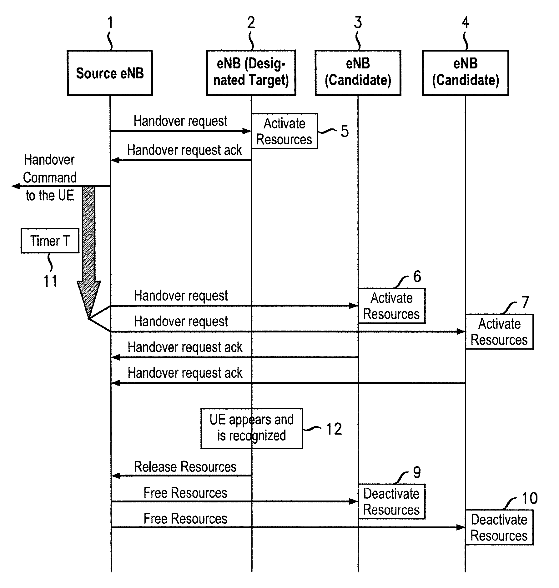
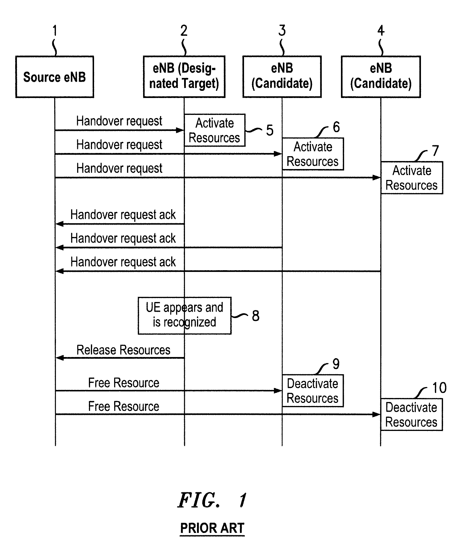
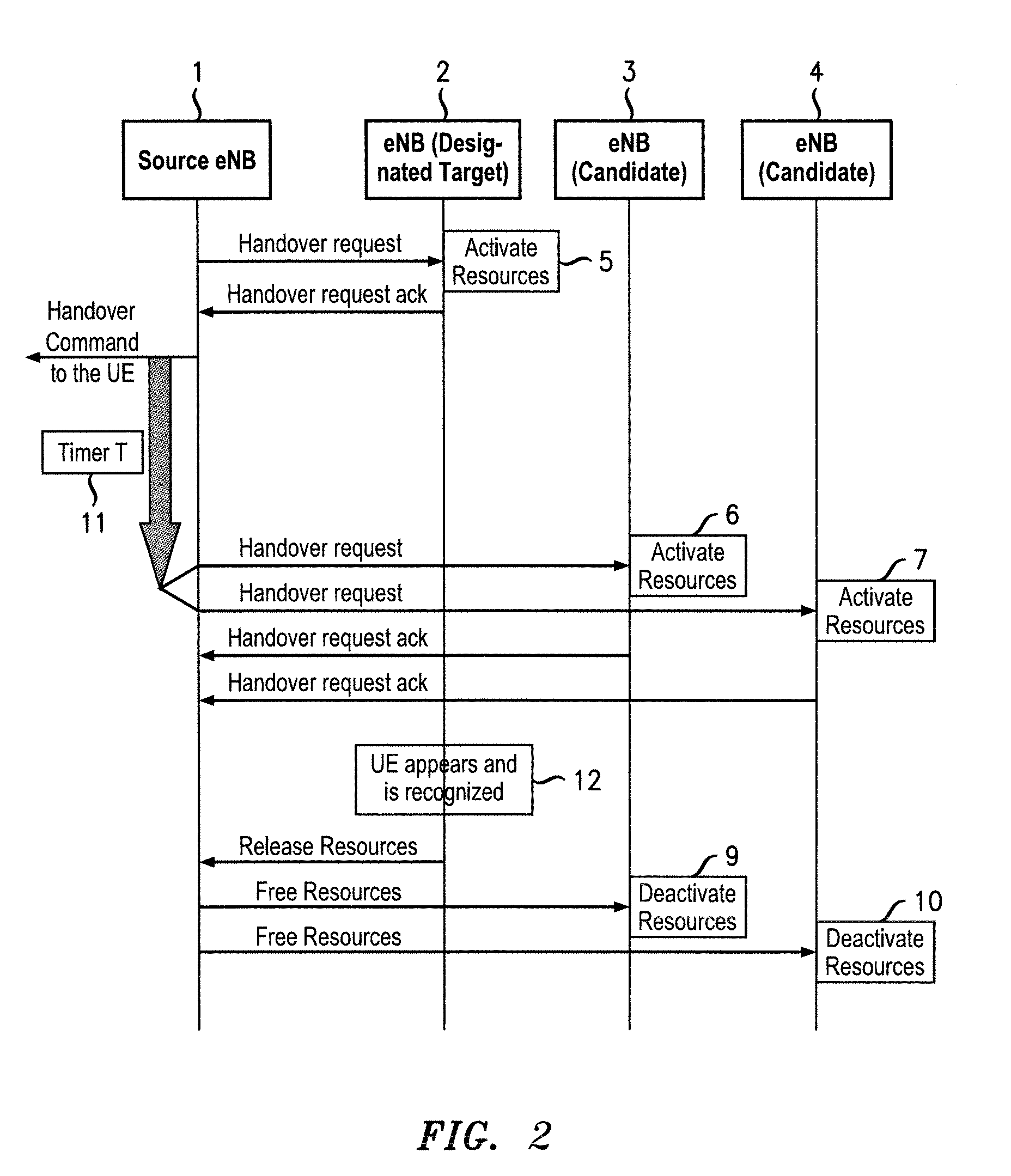
[0011]When there is radio link failure, if the mobile terminal appears in the cell of a network node at which resources have been reserved on request from the source node, that node will recognize the mobile terminal and is able to initiate procedures to complete the connection without this needing to be set up from the beginning. In an LTE network, this avoids the UE entering the IDLE state, and thus reduces the time required to recover a radio link connection with the UE. In an arrangement in accordance with the invention, resources are initially reserved at the target node during RLF, but resources are only reserved at other candidate nodes after a predetermined time period. This deferral of the reservation of resources reduces overheads. For example, in LTE, the Handover_Request message, which instructs the node receiving the message to reserve resources, is delayed for the predetermined specified time period. Then, in the case where the UE re-appears at the source eNB within the first phase of the RLF, and before the time period has expired, no candidate eNBs will have been needlessly prepared and the associated messaging is avoided. In other cases, during RLF, the UE may connect to the designated target eNB at which resources have been reserved and the target node sends a message to the source node to release resources. Candidate eNBs are thus only prepared if the UE fails to either re-attach to the source node or undergo handover to the target node within the predetermined time period. Thus, the signalling load on the X2 interface between eNBs is reduced and resources are reserved at candidate nodes only when they are more likely to be required.

Problems solved by technology

The connection between the UE and the source eNB to which it is attached may be lost, this being known as radio link failure (RLF).
However, this procedure is time-consuming.

Method used


Image

  • Method and apparatus for radio link failure recovery in a wireless communications network
  • Method and apparatus for radio link failure recovery in a wireless communications network
  • Method and apparatus for radio link failure recovery in a wireless communications network

Examples


Embodiment Construction

[0022]With reference to FIG. 2, in an LTE network, a UE (not shown) is connected to a source eNB 1. A Handover_Request message sent to a target eNB 2 and it reserves resources in response, shown at 5: “Activate Resources”. If the target eNB 2 is able to accept the UE, it sends a handover request acknowledgement message to the source eNB 1. The source eNB 1 then sends a Handover_Command to the UE and also triggers a timer T, as shown at 11, which in this arrangement is the timer T1 for RLF in LTE.

[0023]At the expiry of the timer T1, when the predetermined time period has expired, there has been no message sent from the target eNB 2 to the source eNB 1 to indicate that the UE has attached to it. Thus, the source eNB 1 then sends Handover_Request messages to other candidate eNBs 3 and 4. The candidate eNBs 3 and 4 reserve resources, shown at 6 and 7, and send a Handover_Request_Ack message back to the source eNB 1 if they are able to accept the UE. Thus, the Handover_Request message is...


PUM


Abstract

In a method for radio link failure (RLF) recovery in a wireless communications network, a timer T sets a predetermined time period from a command to a mobile terminal UE to hand over to a new eNB. Resources are reserved at a target eNB 2. If the time period expires without the UE attaching to the target eNB 2, the source eNB requests other candidate eNBs 3 and 4 to reserve resources. Once the UE associates with the target eNB 2, the resources reserved at candidate eNBs 3 and 4 are released. If the UE associates with the target eNB 2 prior to expiry of the time period T, resources are not unnecessarily reserved at the candidate eNBs 3 and 4. If the UE associates with one of the candidate eNB 3 instead of the target eNB 2, resources have already been reserved, enabling RLF recovery to be implemented without the UE going via LTE_IDLE, in an LTE arrangement.

Description

FIELD OF THE INVENTION[0001]The present invention relates to a method and apparatus for radio link failure recovery in a wireless communications network, and more particularly, but not exclusively, to a method and apparatus implemented in accordance with the 3rd Generation Partnership Project (3GPP) evolved Universal Terrestrial Radio Access Network (E-UTRAN) and evolved Universal Terrestrial Radio Access (E-UTRA) specifications.BACKGROUND[0002]Currently, 3GPP is considering development of E-UTRA and E-UTRAN as set out in the technical specification 3GPP TS 36.300 v 8.3.0 (2007-12), incorporated herein by way of reference, and related documents. 3GPP Long Term Evolution (LTE) aims to enhance the Universal Mobile Telecommunications System (UMTS) standard, for example, by improving efficiency and services.[0003]In E-UTRAN, user equipment (UE) communicates with a network node, NodeB (eNB), with data being sent on radio bearers (RBs) over a radio link between them. The eNB interfaces wi...

Claims


Application Information

Patent Timeline
IPC IPC(8): H04J1/16H04W36/00G06F11/00
CPCH04W28/26H04W76/028H04W36/0055H04W76/19H04W36/0079
Inventor AYDIN, OSMANKAMINSKI, STEPHEN
Owner ALCATEL LUCENT SAS
Learn More