Method for lightpath monitoring in an optical routing network

Active Publication Date: 2009-08-06
AMERICAN TELEPHONE & TELEGRAPH CO
View PDF4 Cites 71 Cited by
  • Summary
  • Abstract
  • Description
  • Claims
  • Application Information

AI Technical Summary

Benefits of technology

[0008]In accordance with another aspect of the invention, there is disclosed a system for enabling light path monitoring in an optical network. The system generally comprises: a polarization modulator/scrambler for introducing a pilot tone signal as an overlay on a plurality of optical signals from a source node; and a performance monitoring unit for detecting the pilot tone signal to enable light path monitoring and identification through the optical network.
[0009]In accordance with yet another aspect of the invention, there is disclosed a system for simultaneous light path, channel power, polarization mode dispersion (PMD) and in-band optical signal-to-noise ratio (OSNR) monitoring in an optical network. The system generally comprises: a polarization modulator/scrambler for introducing a pilot tone signal as an overlay on a plurality of optical s

Problems solved by technology

This method has the advantages of modulation-format transparency and simplicity (for amplitude-based pilot tone), but it also suffers serious drawbacks.
For example, amplitude-modulation based pilot tone methods suffer from Stimulated Raman Scattering (SRS) crosstalk.
These expedients are much more expensive to implement than amplitude pilot tone techniques since each signal requires an independent phase/frequency or po

Method used


Image

  • Method for lightpath monitoring in an optical routing network
  • Method for lightpath monitoring in an optical routing network
  • Method for lightpath monitoring in an optical routing network

Examples


Embodiment Construction

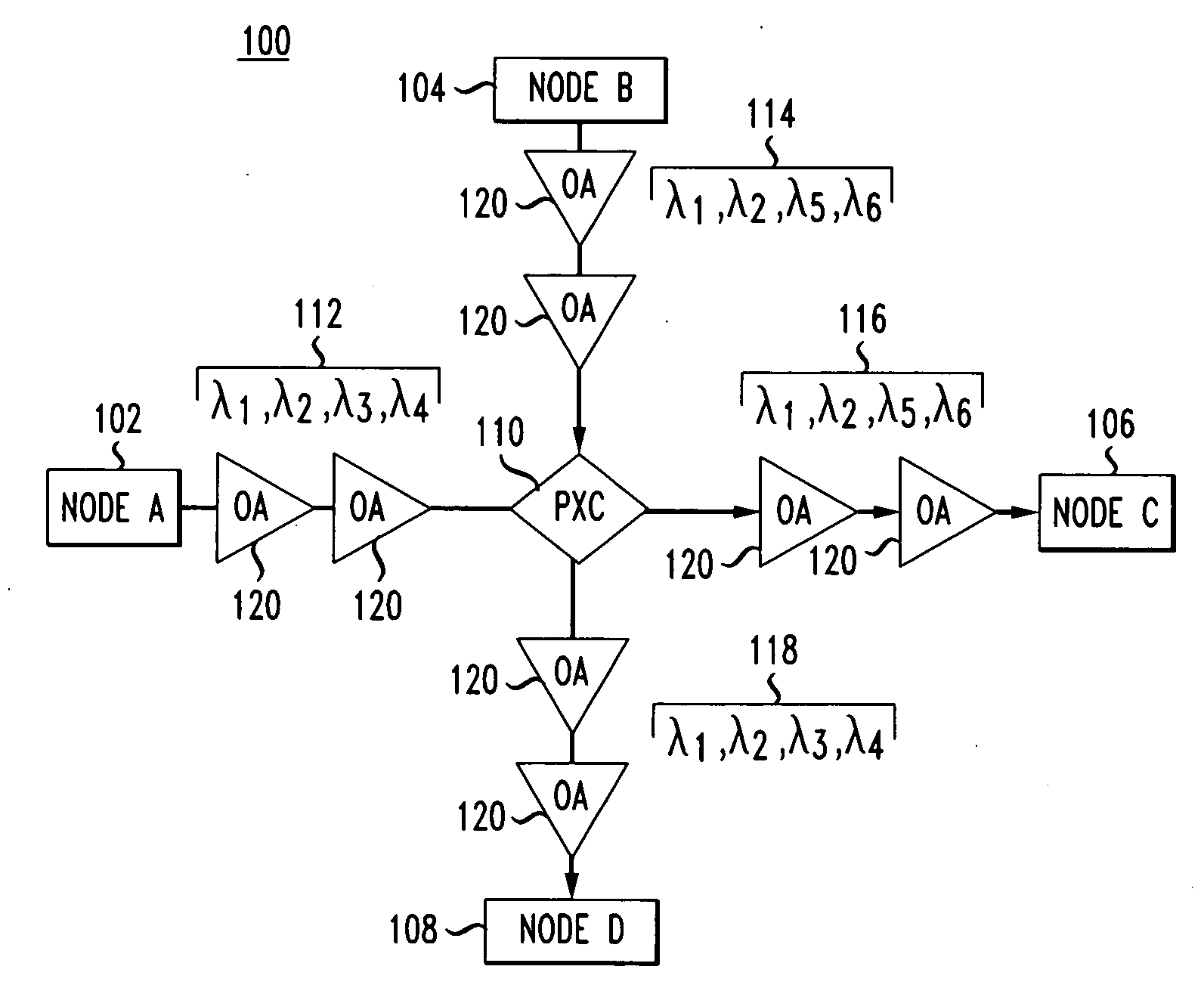
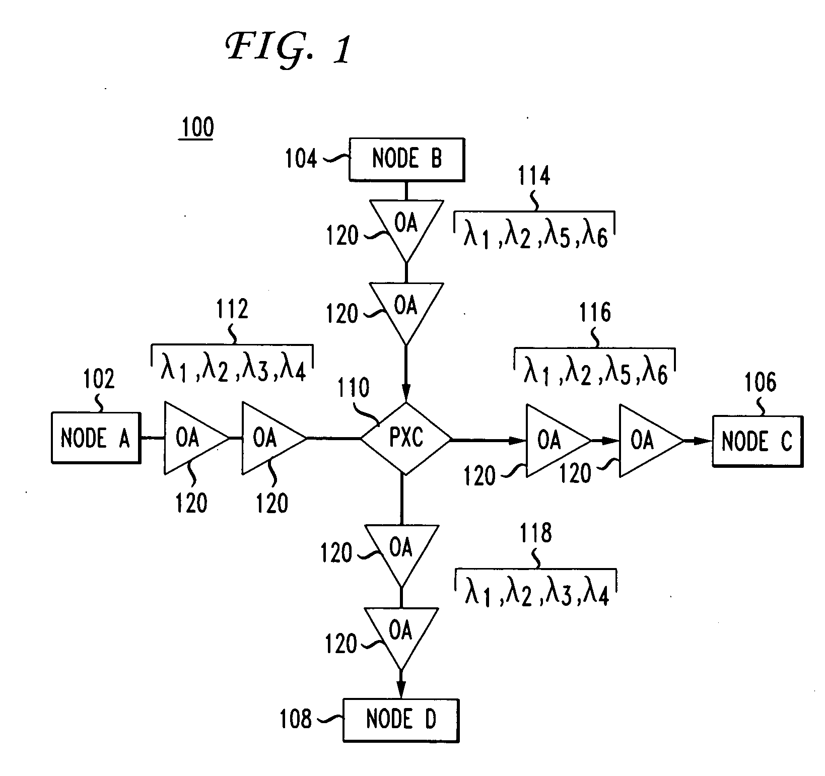
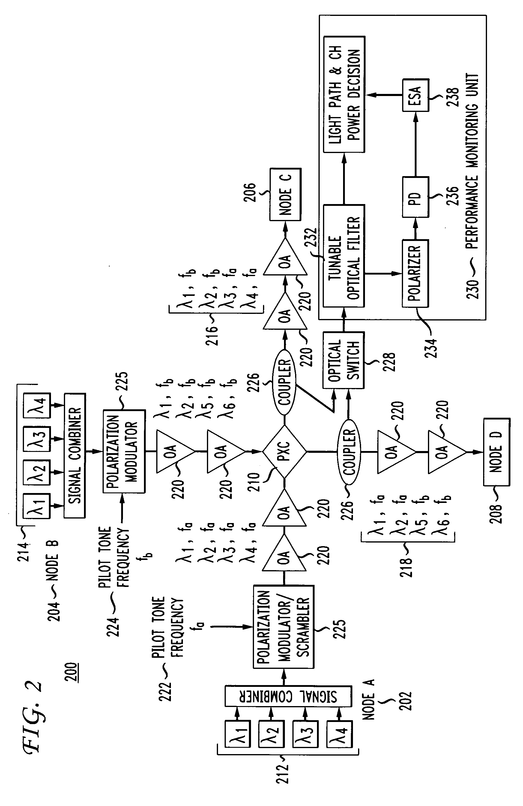
[0015]Embodiments of the invention will be described with reference to the accompanying drawing figures wherein like numbers represent like elements throughout. Before embodiments of the invention are explained in detail, it is to be understood that the invention is not limited in its application to the details of the examples set forth in the following description or illustrated in the figures. The invention is capable of other embodiments and of being practiced or carried out in a variety of applications and in various ways. Also, it is to be understood that the phraseology and terminology used herein is for the purpose of description and should not be regarded as limiting. The use of “including,”“comprising,” or “having” and variations thereof herein is meant to encompass the items listed thereafter and equivalents thereof as well as additional items.

[0016]This invention proposes a new modulation-format-transparent method and system for lightpath monitoring, which overlays a char...


PUM


Abstract

A method and system for enabling lightpath monitoring in an optical network is disclosed. A single polarization modulator/scrambler introduces a pilot tone signal as an overlay on a plurality of optical signals on a source node and a performance monitoring unit detects the pilot tone signal to enable light path monitoring and identification through the optical network.

Description

FIELD OF THE INVENTION[0001]The present invention relates generally to monitoring the status of an optical network, and more particularly, to a new method for lightpath monitoring by overlaying a characteristic polarization pilot tone frequency on an optical signal(s) and detecting the same in the electrical domain. This expedient provides a unique in-band lightpath label for lightpath tracing and identification in an optical-routing network.BACKGROUND OF THE INVENTION[0002]Optical networks using Remotely configurable Optical Add / Drop Multiplexers (ROADMs) or Photonic Cross Connects (PXCs) to optically route are commonly deployed in optical networks, and provide the benefits of lower cost, greater flexibility in data formats, and hitless capacity upgrades. In such networks, the signals may remain in the optical domain for thousands of km, passing through many optical amplifiers (OAs) and multiple ROADMs / PXCs (nodes). To operate such a network successfully on a large scale, a new sui...

Claims


Application Information

Patent Timeline
IPC IPC(8): H04B10/08
CPCH04B2210/075H04B10/0773
Inventor ZHOU, XIANGFEUER, MARK DAVID
Owner AMERICAN TELEPHONE & TELEGRAPH CO
Why Eureka
Try Eureka