
Distortion compensation circuit and method based on orders of time dependent series of distortion signal

a compensation circuit and distortion signal technology, applied in the field of distortion compensation, can solve the problems of non-linear elements contributing to distortion, predistortion circuits may not adequately compensate for frequency-dependent distortion, and dependent distortion characteristics

Active Publication Date: 2009-08-06
APPLIED OPTOELECTRONICS
View PDF27 Cites 22 Cited by
  • Summary
  • Abstract
  • Description
  • Claims
  • Application Information

AI Technical Summary

Problems solved by technology

The use of a directly-modulated laser to carry a wide-band RF signal may result in distortion due to the multiple carrier frequencies of the multichannel RF signal modulating the laser and / or the harmonics produced by the non-linear nature of the laser device.
However, some non-linear elements, such as lasers, have time dependence and thus have distortion characteristics dependent on the frequency of the modulating signal.
However, such existing predistortion circuits may not adequately compensate for the frequency-dependent distortion.
Further, other non-linear elements may also contribute to distortion.

Method used


Image

  • Distortion compensation circuit and method based on orders of time dependent series of distortion signal
  • Distortion compensation circuit and method based on orders of time dependent series of distortion signal
  • Distortion compensation circuit and method based on orders of time dependent series of distortion signal

Examples


Embodiment Construction

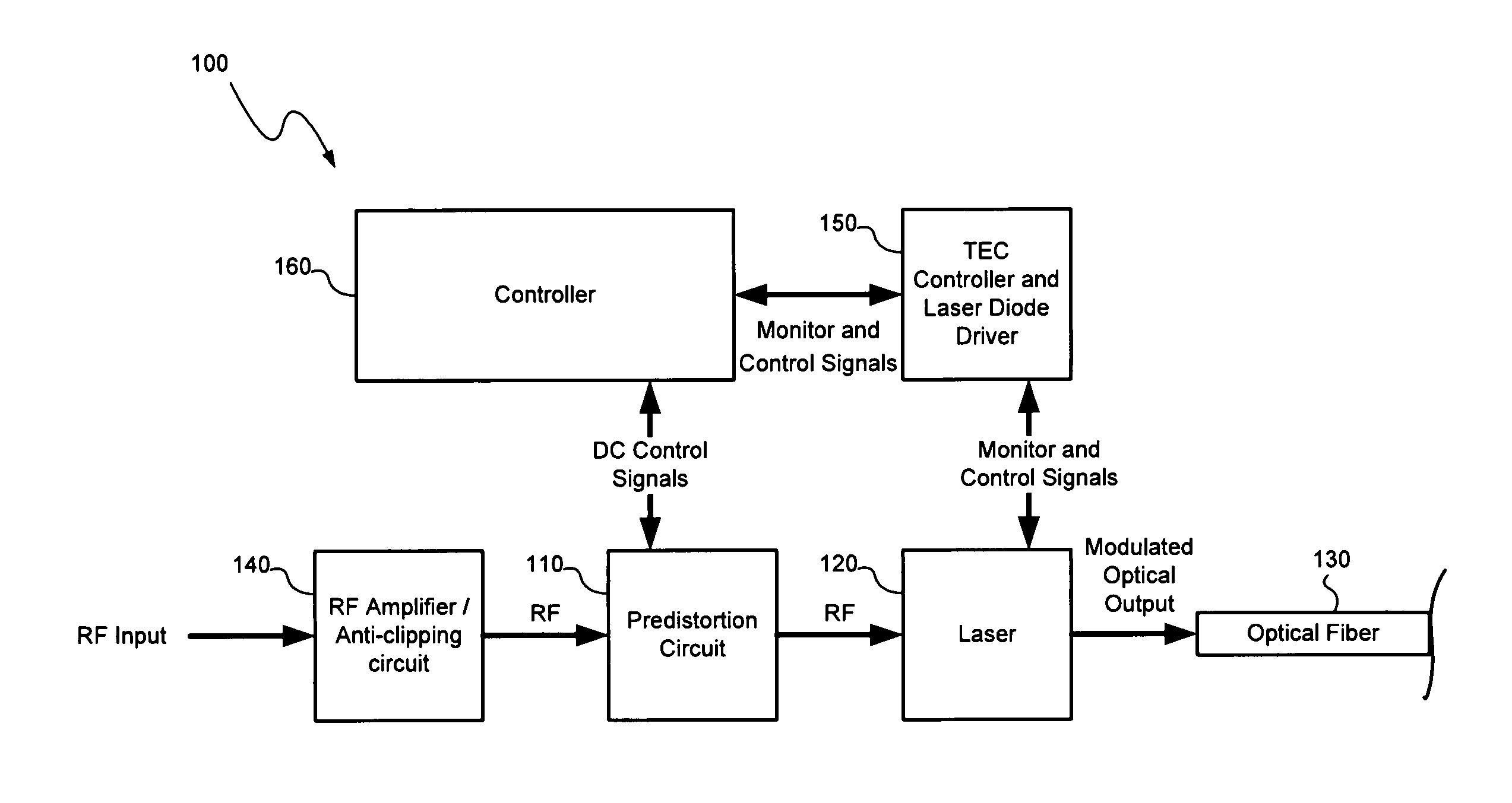
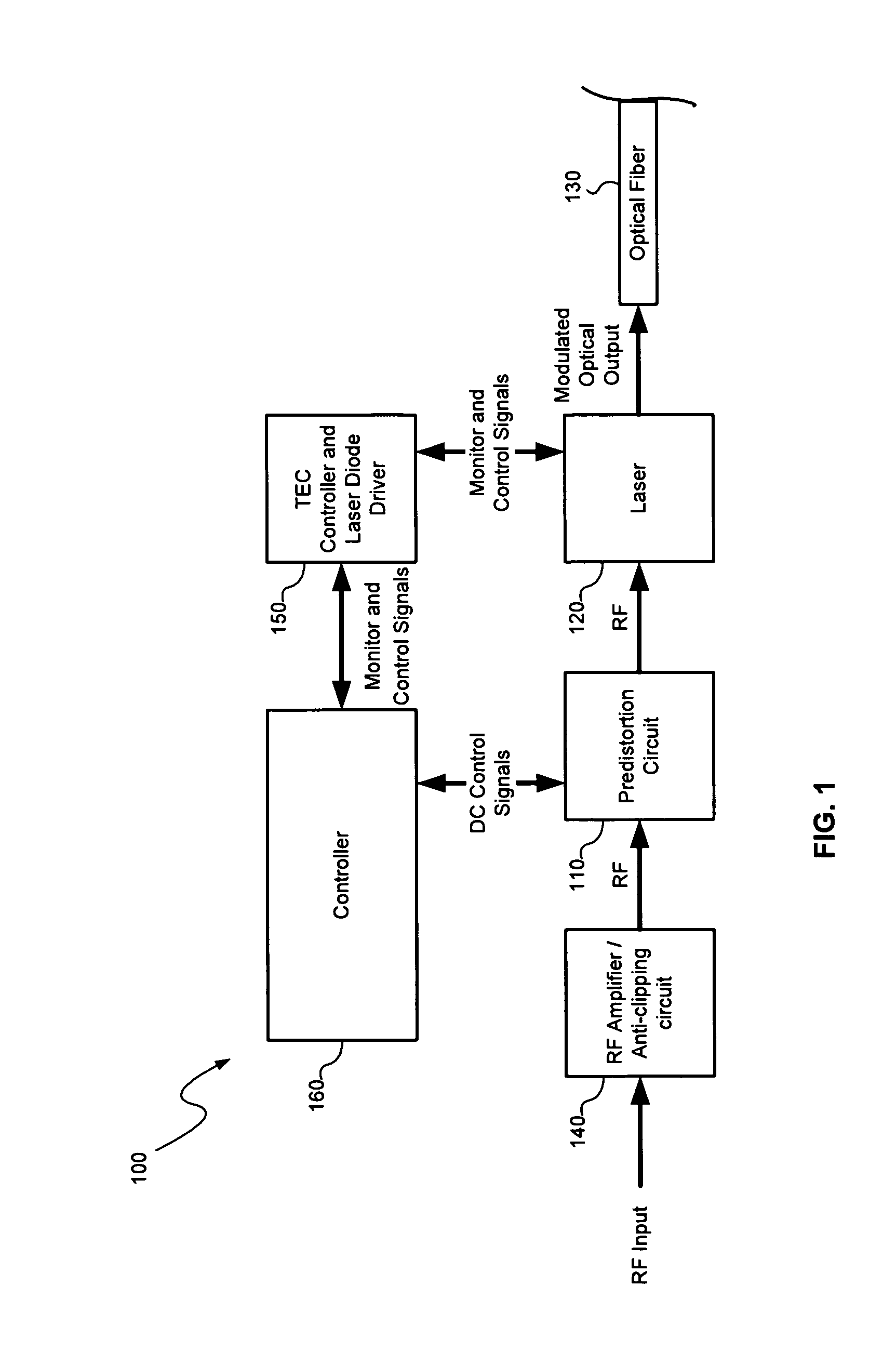
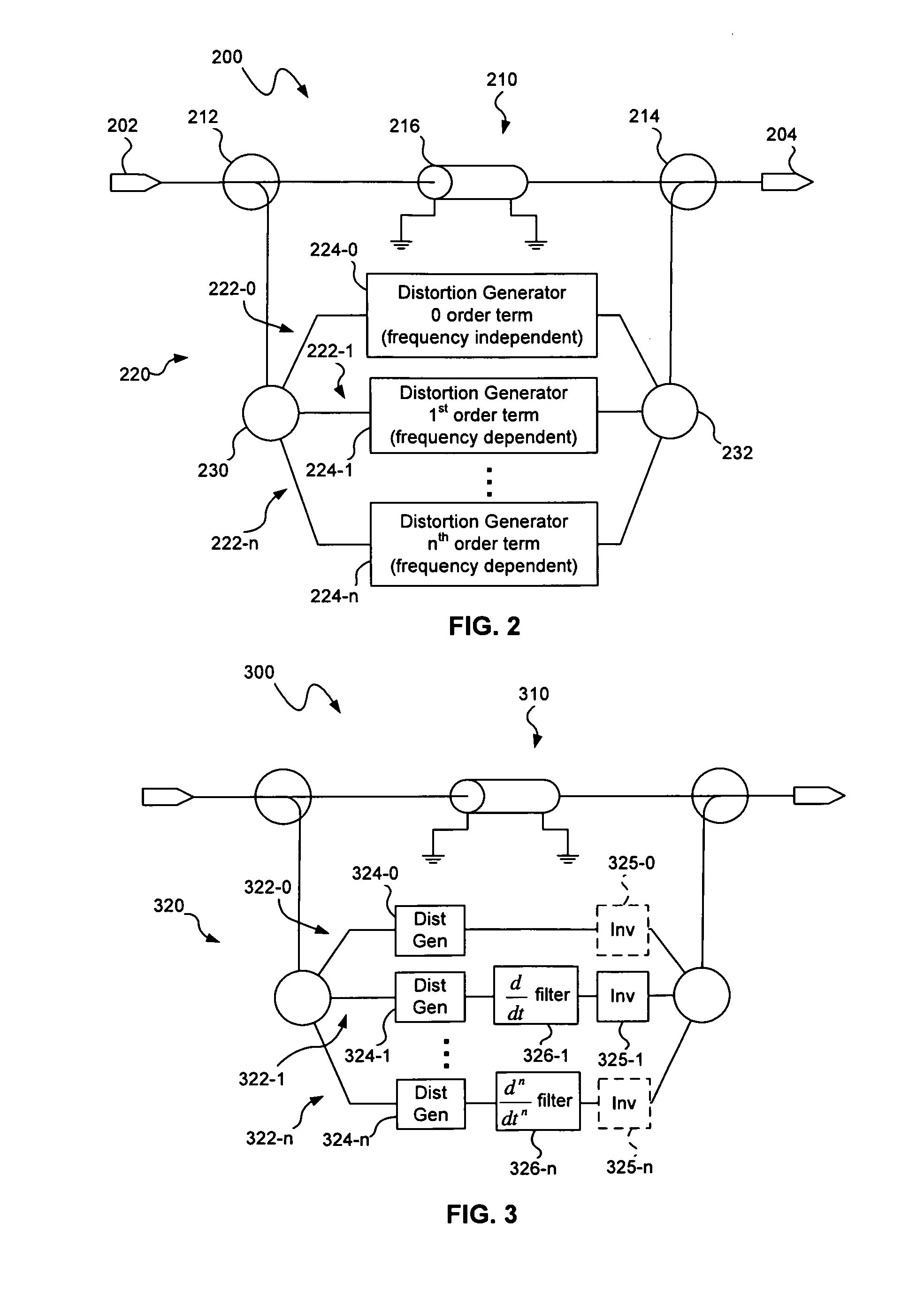
[0018]A distortion compensation circuit, consistent with embodiments of the present invention, may be used with one or more non-linear elements, such as a laser, to compensate for distortion generated by the non-linear element(s), for example, in broadband applications. As will be described in greater detail below, embodiments of the distortion compensation circuit may include a plurality of distortion paths corresponding to different frequency dependent orders of a time dependent series of a distortion signal. The distortion compensation circuit may include, for example, a frequency independent distortion path and one or more frequency dependent distortion paths to produce distortion that compensates for frequency dependent distortion generated by the non-linear element(s).

[0019]Distortion compensation circuits may include predistortion circuits, which generate compensating distortion before the non-linear element(s), for example, in an optical transmitter. Distortion compensation ...


PUM


Abstract

A distortion compensation circuit compensates for distortion generated by one or more non-linear elements such as a laser device. The distortion compensation circuit may be used in an optical transmitter, such as a laser transmitter used for forward path CATV applications. The distortion compensation circuit may include a primary signal path and a secondary signal path that receive an input signal. The secondary signal path produces distortion of a magnitude corresponding to the magnitude of, but at an opposite phase to, the distortion generated by the non-linear amplifier. The secondary signal path includes a plurality of distortion sub-paths with each of the distortion sub-paths configured to produce intermodulation distortion products of the same distortion order but for different frequency dependent orders in a time dependent series representative of the distortion produced by the non-linear amplifier.

Description

TECHNICAL FIELD[0001]The present invention relates to distortion compensation and more particularly, to a distortion compensation circuit and method based on orders of time dependent series of distortion signal.BACKGROUND INFORMATION[0002]A directly modulated laser may be used as an optical transmitter that transmits light at a given wavelength. The power (i.e., amplitude) of the laser light is modulated by corresponding modulation of the current used to drive the laser. For example, the optical transmitter may be modulated to carry a wide-band RF signal. In this case, the electrical current that drives or pumps the laser is modulated with the wide-band RF signal.[0003]The use of a directly-modulated laser to carry a wide-band RF signal may result in distortion due to the multiple carrier frequencies of the multichannel RF signal modulating the laser and / or the harmonics produced by the non-linear nature of the laser device. Intermodulation distortion may be produced when two or mor...

Claims


Application Information

Patent Timeline
Patent Type & Authority Applications(United States)
IPC IPC(8): H04B10/04
CPCH04B10/58H04B10/504
Inventor ZHENG, JUNISHAUG, BRIAN
Owner APPLIED OPTOELECTRONICS
Learn More