Continuous flow ultra-centrifugation systems

a technology of ultra-centrifugation and continuous flow, which is applied in the direction of centrifuges, instruments, computing, etc., can solve the problems of large floor space, failure of vacuum seals, and system size,

Active Publication Date: 2009-08-06
ALFA WASSERMANN INC
View PDF15 Cites 11 Cited by
  • Summary
  • Abstract
  • Description
  • Claims
  • Application Information

AI Technical Summary

Benefits of technology

[0011]In some embodiments, the stator housing can include a stator cooling chamber and the system can include a vapor-compression-cooling system that pumps a refrigerated coolant into the stator cooling chamber. The stator cooling chamber and the refrigerated coolant can be sufficient to prevent heating of a heating product within the system by more than about 4.0 degrees.

Problems solved by technology

Unfortunately, such prior art continuous flow ultra-centrifugation systems have several common disadvantages.
One common disadvantage is the size of the system, which often requires significant floor space.
Another common disadvantage relates to the failure of the vacuum seals, which are located around the high-speed drive spindle.
Yet another common disadvantage relates to the amount of heat generated and transferred to the solution and its constituents during the centrifugation process.

Method used


Image

  • Continuous flow ultra-centrifugation systems
  • Continuous flow ultra-centrifugation systems
  • Continuous flow ultra-centrifugation systems

Examples


Embodiment Construction

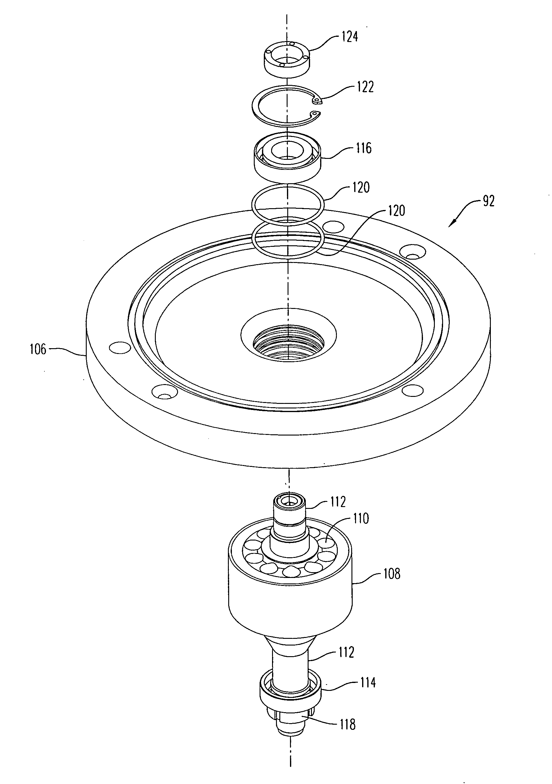
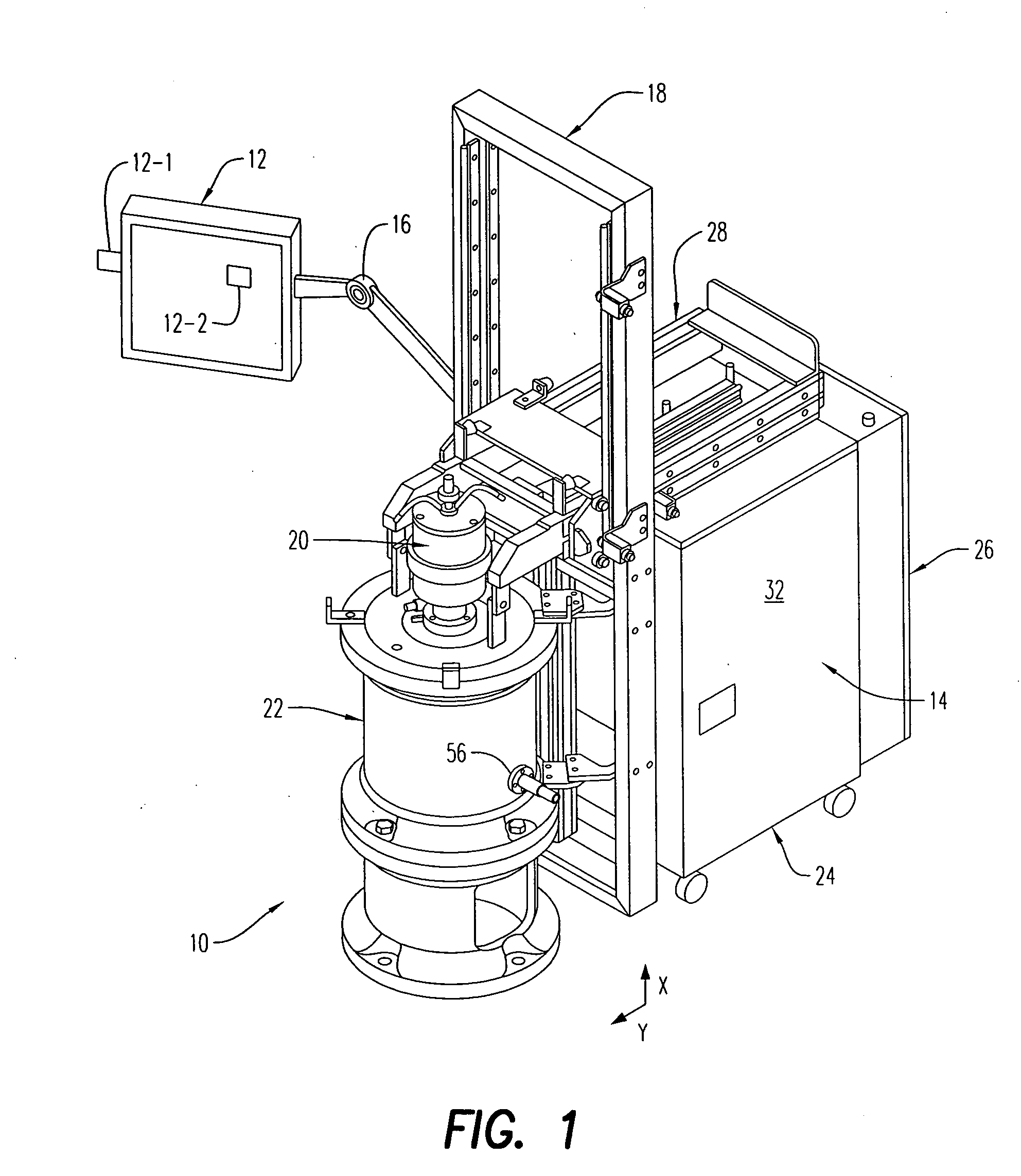
[0034]Referring to the drawings and in particular to FIG. 1, an exemplary embodiment of a continuous flow ultra-centrifugation system according to the present disclosure is shown and is generally referred to by reference numeral 10.

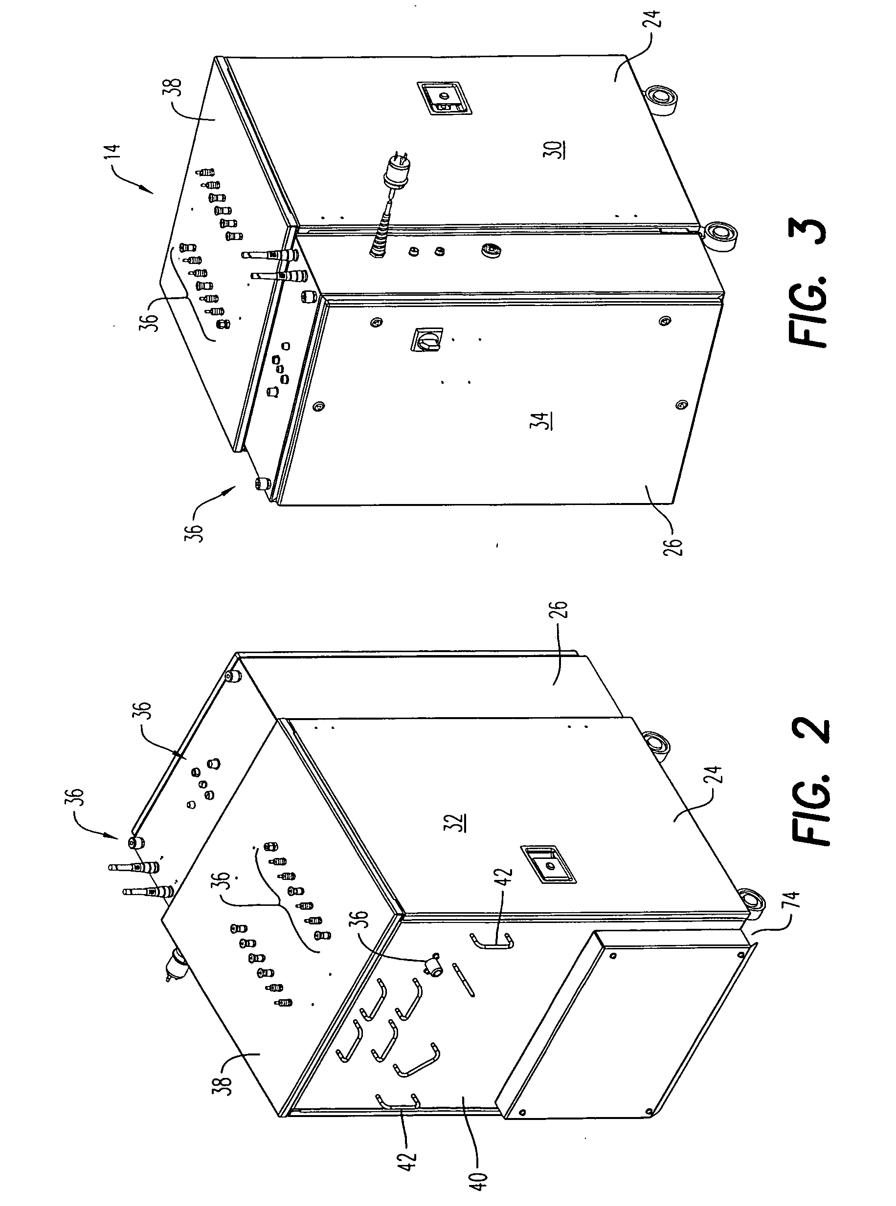
[0035]Continuous flow ultra-centrifugation system 10 (hereinafter “system”) includes a control interface 12, a control cabinet 14, a lift assembly 18, a drive assembly 20, and a centrifugation tank assembly 22.

[0036]Control interface 12 is secured to lift assembly 18 by an arm 16. In the illustrated embodiment, arm 16 is a moveable arm that allows an operator move the control interface to a desired position with respect to system 10. Of course, it is contemplated by the present disclosure for control interface 12 to be secured to any component of system 10 such as, but not limited to, control cabinet 14, drive assembly 20, centrifugation tank assembly 22, and any combinations thereof.

[0037]Control interface 12 is in electrical communication with, for exam...


PUM


Abstract

A continuous flow centrifuge system is provided. The system includes a rotor, a stator, a stator housing, upper and lower bearing plates, upper and lower bearings, first and second snap rings, and lip seal. The upper bearing rotatably secures a shaft of the rotor in the upper bearing plate. The first snap ring secures the upper bearing to the rotor shaft. The lip seal is over the upper bearing and forms a rotatable seal with the upper bearing plate. The second snap ring secures the lip seal to an inner diameter of the upper bearing plate. The upper and lower bearing plates are secured to the stator housing so that the rotor is operatively aligned with the stator.

Description

CROSS REFERENCE TO RELATED APPLICATIONS[0001]This application claims the benefit of U.S. Provisional Application Ser. No. 61 / 008,902, filed Dec. 21, 2007 the contents of which are incorporated by reference herein.BACKGROUND OF THE INVENTION[0002]1. Field of the Invention[0003]The present disclosure relates to continuous flow ultra-centrifugation systems. More particularly, the present disclosure relates to continuous flow ultra-centrifugation systems having an electric drive assembly.[0004]2. Description of Related Art[0005]Centrifugal separation is commonly used to separate a solution into its constituent parts based on the density of the constituents. Here, the centrifugation system creates a centrifugal force field by spinning the solution containing the constituents to be separated, thus causing the constituents of higher density to separate from the solution.[0006]Many different styles of centrifugation systems have been used and are typically classified by, among other things,...

Claims


Application Information

Patent Timeline
Patent Type & Authority Applications(United States)
IPC IPC(8): B04B9/10B04B7/08B04B15/02B04B9/06B04B13/00
CPCB04B7/02B04B9/12B04B9/04B04B15/02B04B13/00B04B7/06B04B15/06B04B15/08G06F3/04817G06F3/0488
Inventor SPIEGEL, KURTWEISSMAN, SORINLEPSE, BILLMARSH, BLAINE J.
Owner ALFA WASSERMANN INC
Why Eureka
Try Eureka