
In vivo imaging system

a technology imaging system, which is applied in the field of in vivo imaging system, can solve the problems of difficult to obtain views of the patient's interior, a great invasion of the patient's body,

Inactive Publication Date: 2009-08-06
MYERS STEPHEN R
View PDF17 Cites 6 Cited by
  • Summary
  • Abstract
  • Description
  • Claims
  • Application Information

AI Technical Summary

Problems solved by technology

While such extra ports are useful, they result in greater invasion of the patient's body, and some views of the patient's interior might still be difficult to obtain.

Method used


Image

  • In vivo imaging system
  • In vivo imaging system
  • In vivo imaging system

Examples


Embodiment Construction

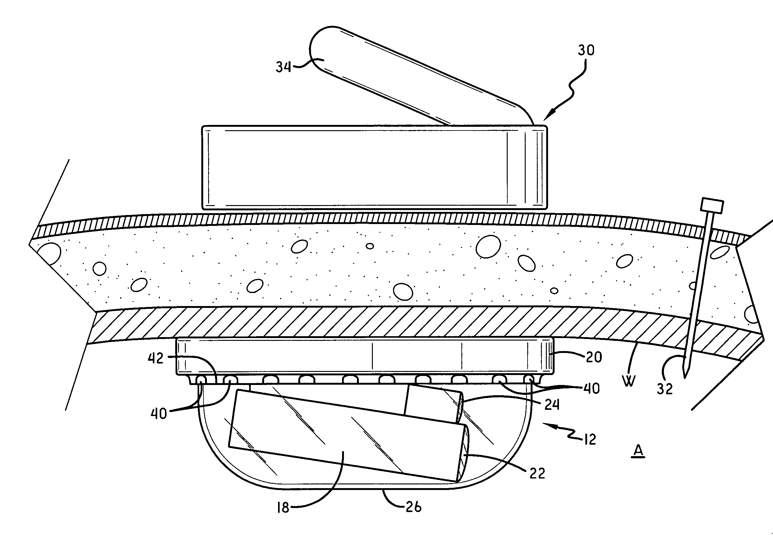
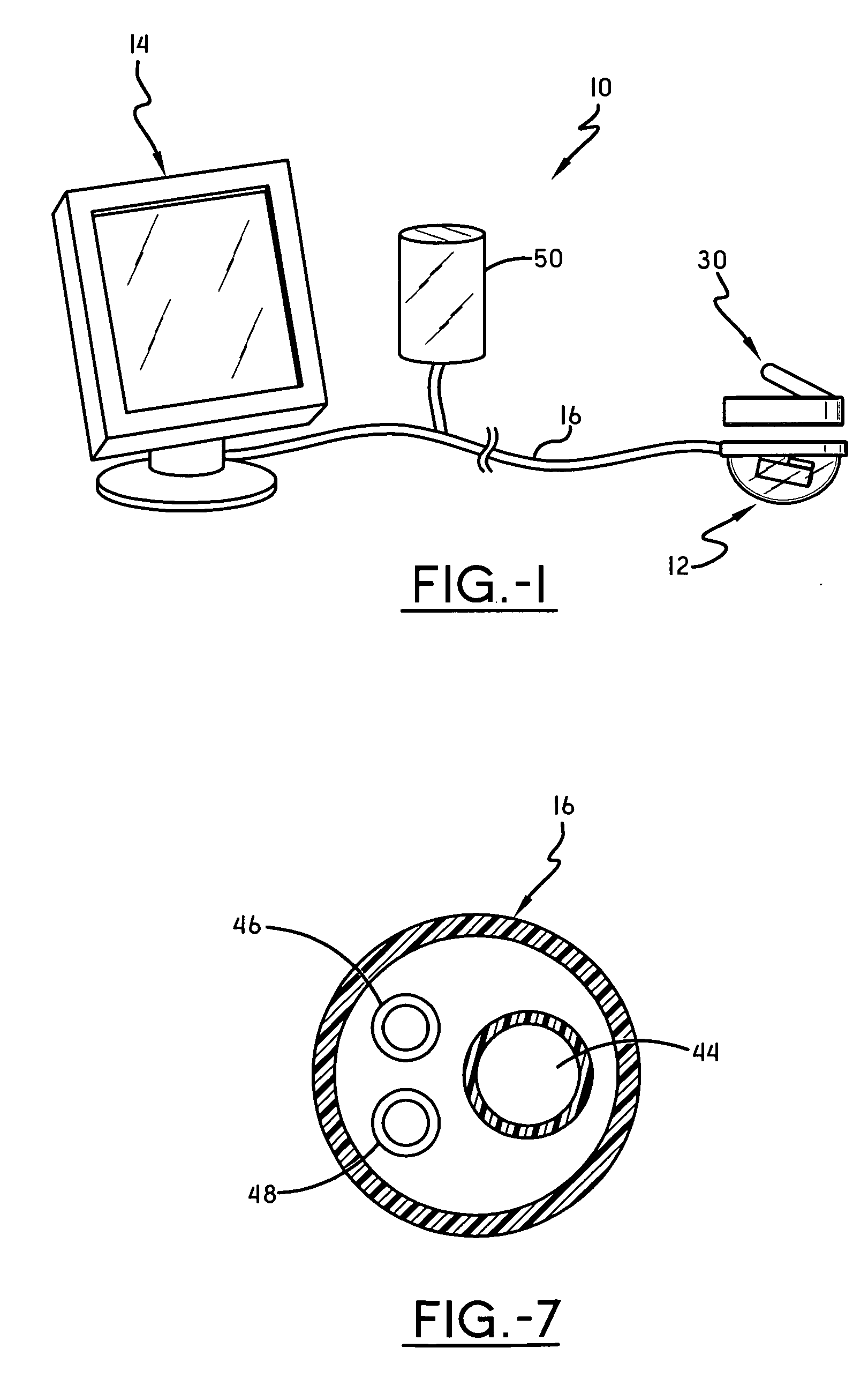
[0017]Referring now to FIG. 1, an embodiment of an in vivo imaging system in accordance with this invention is shown and designated by the numeral 10. Imaging system 10 includes a camera assembly 12, which is intended to be introduced to an in vivo site. Camera assembly 12 communicates with an image display device 14, through a cable 16 so that images received by the camera assembly 12 can be displayed. Cable 16 would also preferably provide power to the camera assembly and may provide other functionalities, as will be described below.

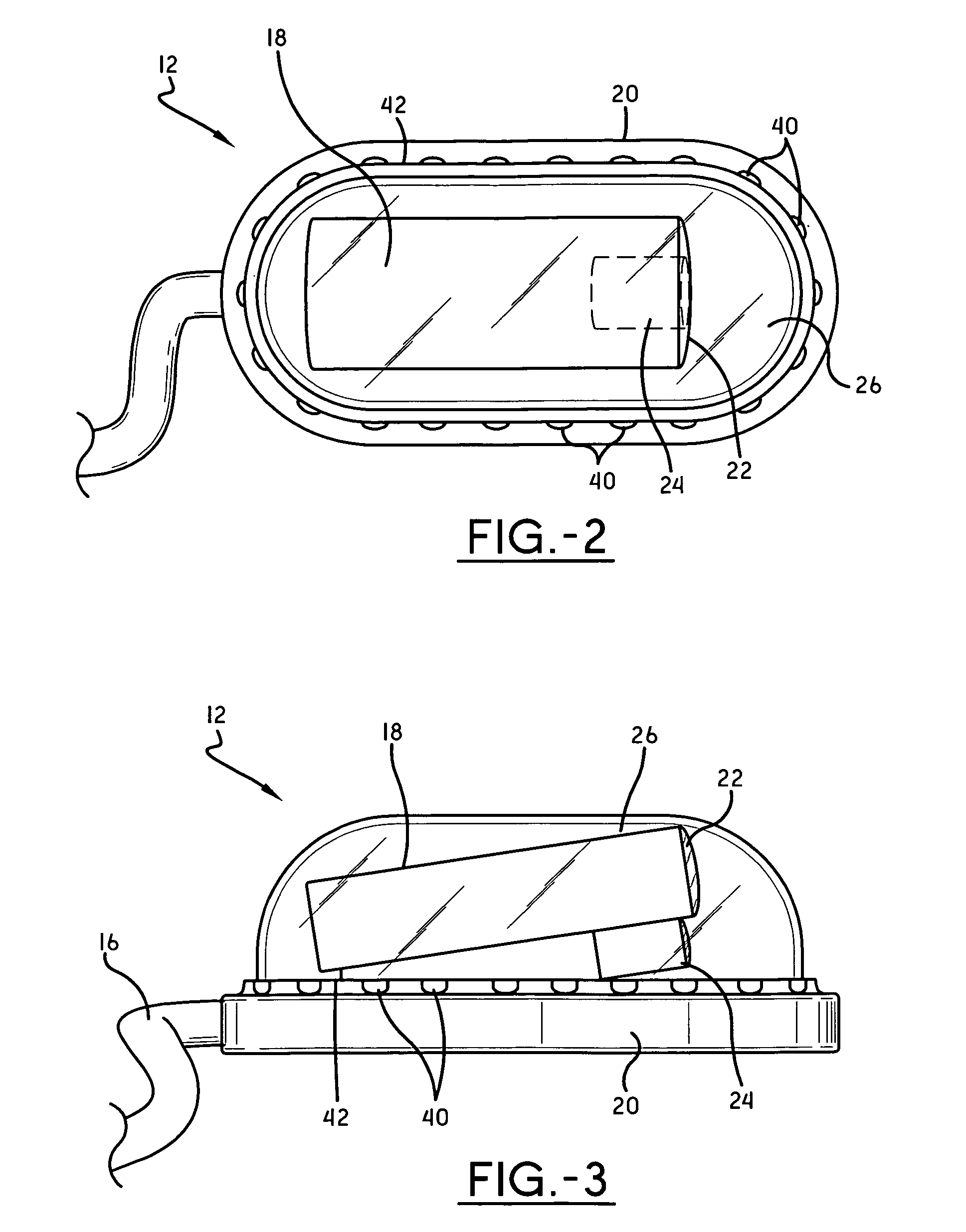
[0018]Referring now to FIGS. 2 and 3, camera assembly 12 includes a camera 18 that is secured to a sled body 20. Camera 18 includes a lens 22 having a viewing angle for taking in images and transmitting them to the image display device 14. As known, the viewing angle of the lens 22 could be made adjustable or fixed, with or without zoom capabilities and the like. Because the camera assembly 12 is targeted for placement in an in vivo site, a light 24 is...


PUM


Abstract

An in vivo imaging system for viewing the interior of an organism includes a camera mounted to a sled body that is placed in the interior of the organism. The camera includes a lens, and a dome covers the lens. An image display device is provided to display images received from the camera. A cable communicates images to the image display device according to a viewing angle of the lens. A magnetic source body placed on the exterior of the organism magnetically attracts the sled body to hold the sled body in place in the interior of the organism.

Description

BACKGROUND OF THE INVENTION[0001]Over the last few decades, surgery at in vivo sites (herein to be understood as a location inside an organism) has been revolutionized by the use of the laparascope. The laparascope is an imaging device that has led to the development of minimally invasive surgery procedures because it can transmit images from an in vivo site, permitting a surgeon to view and operate at the in vivo site without having to directly view the site by cutting the patient open. Instead, several small incisions are made in the skin, and specialized tubes or ports are placed therein to accept passage of the laparoscope and other long narrow instruments employed in the operation being performed.[0002]In complex operations, it is common to have multiple ports for the passage of the laparoscope. This ensures that different viewing angles can be recorded by the laparoscope to help visualize the operations taking place in vivo. While such extra ports are useful, they result in gr...

Claims


Application Information

Patent Timeline
Patent Type & Authority Applications(United States)
IPC IPC(8): A61B1/05
CPCA61B1/00158A61B1/041A61B19/5225A61B2017/00876A61B2019/2253A61B2017/00283A61B34/73A61B90/37
Inventor MYERS, STEPHEN R.
Owner MYERS STEPHEN R
Learn More