Spinous process spacer

a technology of process spacer and spacer, which is applied in the field of spinous process spacer, can solve problems such as postoperative displacement, and achieve the effect of preventing timewise postoperative displacemen

Inactive Publication Date: 2009-08-06
OLYMPUS TERUMO BIOMATERIALS
View PDF6 Cites 16 Cited by
  • Summary
  • Abstract
  • Description
  • Claims
  • Application Information

AI Technical Summary

Benefits of technology

[0030]The present invention demonstrates effects in which the spacer can be stably inserted and fixed between split faces of a split spinous process i...

Problems solved by technology

In such a case, the split faces of the spinous process and the spinous process spacer are in contact with each other in extremely small contact areas, and their contact condition is unstable, which may cause postoperative ...

Method used


Image

  • Spinous process spacer
  • Spinous process spacer
  • Spinous process spacer

Examples


Embodiment Construction

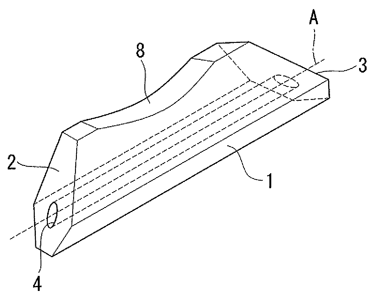
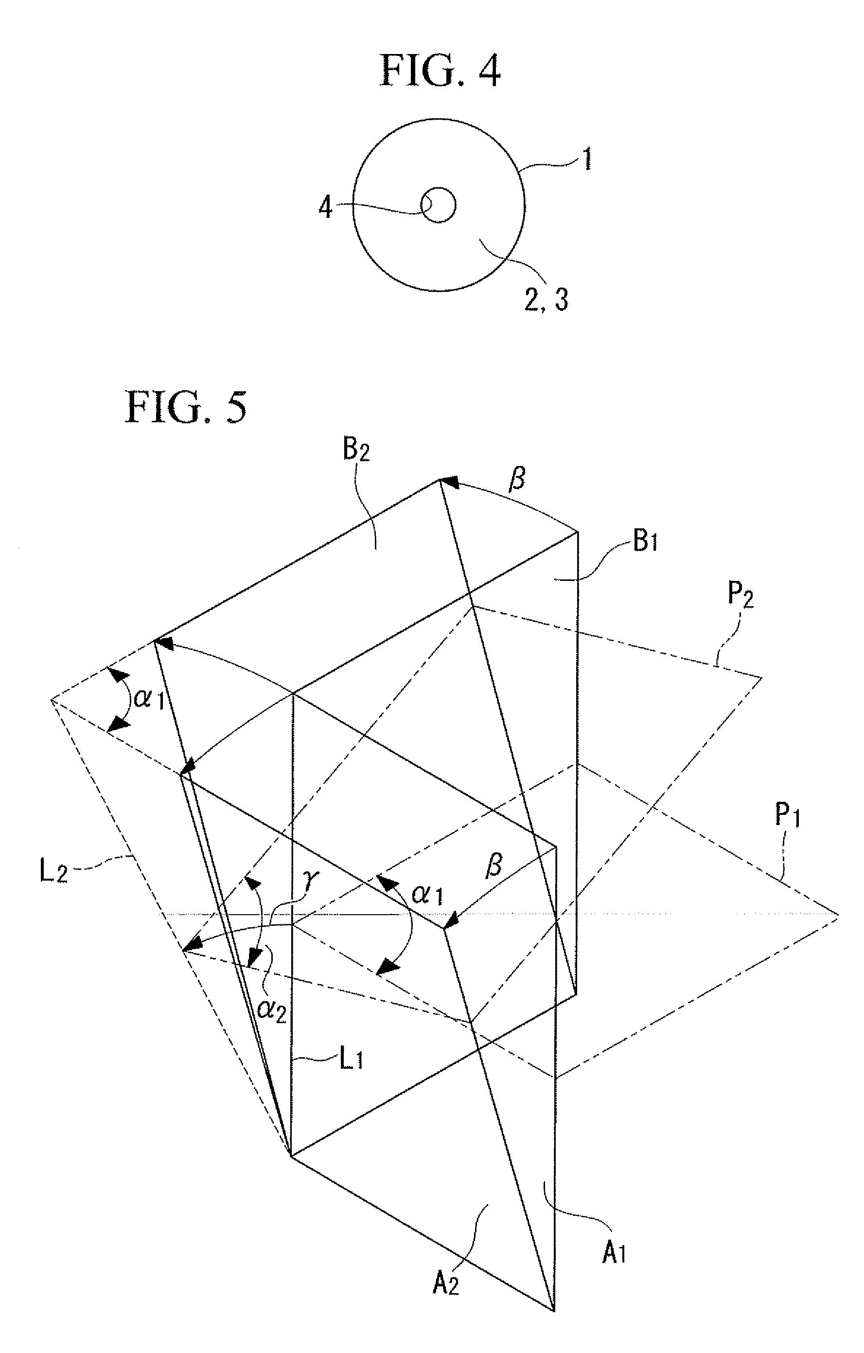
[0047]Hereunder is a description of a spinous process spacer 1 according to a first embodiment of the present invention, with reference to FIG. 1 to FIG. 5.

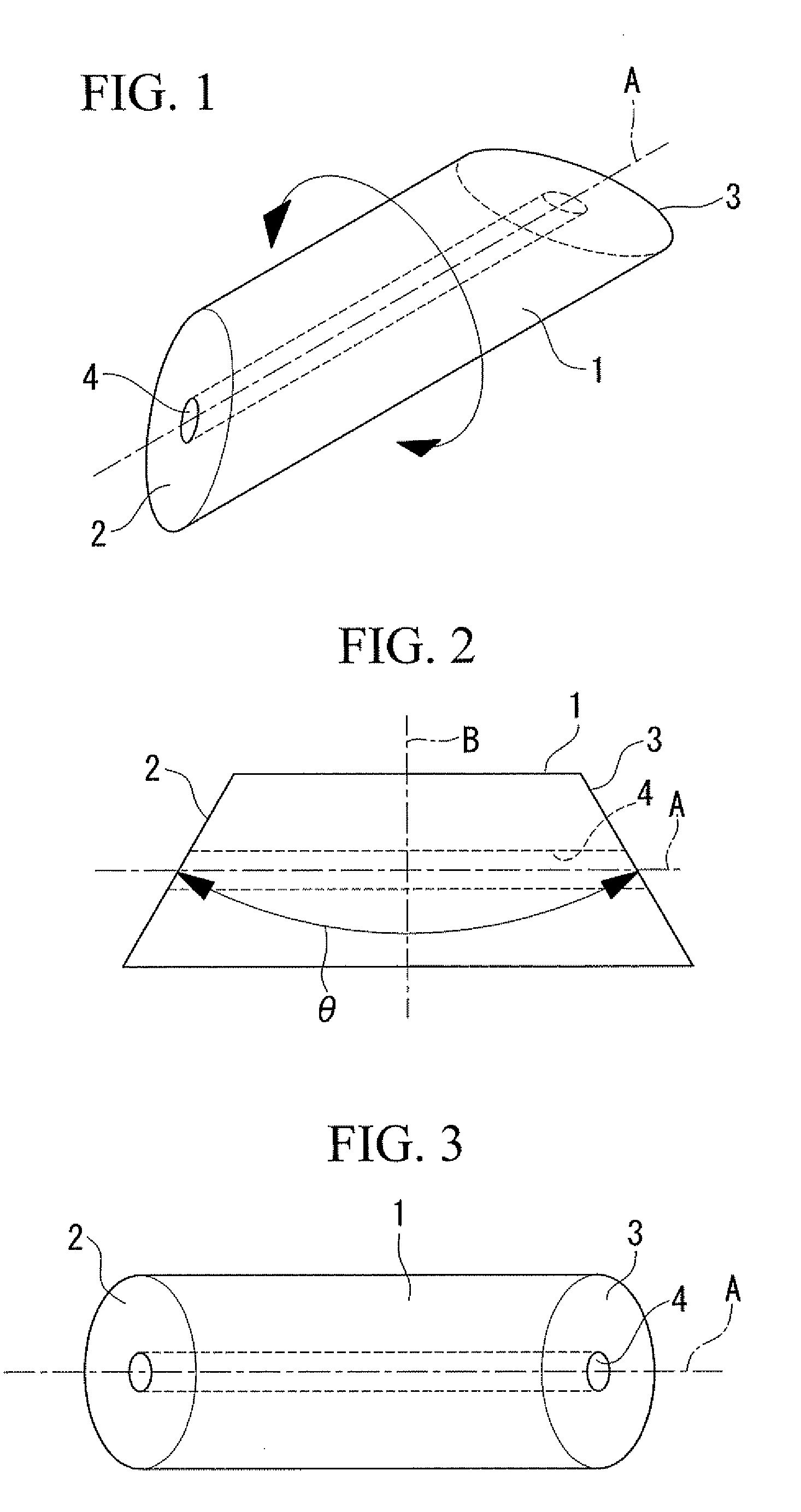
[0048]As shown in FIG. 1, the spinous process spacer 1 according to the present embodiment is made of cylindrical shaped calcium phosphate wherein opposite end faces 2 and 3 thereof are inclined with respect to the central axis A.

[0049]As shown in FIG. 2, the opposite end faces 2 and 3 are constituted by planes which are inclined respectively in reverse directions at a same angle with respect to the central axis A. Therefore, the spinous process spacer 1 according to the present embodiment has mirror symmetry about a plane B which passes through the longitudinal center and is orthogonal to the central axis A. The angle θ formed by these two end faces 2 and 3 is set at an angle selected from a range of not smaller than 30° and not larger than 90°, for example.

[0050]As a result, the spinous process spacer 1 according to the present...


PUM


Abstract

To provide a spinous process spacer that can be stably inserted and fixed between split faces of a split spinous process in a gapless manner, without made-to-order production for each patient. There is provided a spinous process spacer (1) for insertion between split halves of a spinous process resulting from longitudinal splitting of the spinous process, wherein the spinous process spacer is formed in an approximately cylindrical shape and the opposite end faces (2, 3) thereof are constituted by planes which mutually form a fixed angle.

Description

TECHNICAL FIELD[0001]The present invention relates to a spinous process spacer for insertion between split halves of a spinous process resulting from longitudinal splitting of the cervical spinous process.BACKGROUND ART[0002]Conventionally, foraminotomy has been conducted for relieving impairments caused by compression on the spinal cord due to cervical spondylotic myelopathy or ossification of posterior longitudinal ligament. Double-door laminoplasty by midline splitting of spinous processes has been known in which spinous process spacers are inserted between split halves of spinous processes formed by longitudinal splitting of the spinous processes (for example, refer to Patent Document 1).[0003]As a spinous process spacer to be used for this double-door laminoplasty, Patent Document 1 has disclosed a block-shaped spinous process spacer in which mutually orthogonal cross sections of two directions (horizontal cross section and longitudinal front forehead cross section) are both fo...

Claims


Application Information

Patent Timeline
IPC IPC(8): A61B17/70
CPCA61B17/7071A61F2/44
Inventor SHIBATA, KOICHIIRIE, HIROYUKIURATA, MITSUYAOJIMA, SATOSHI
Owner OLYMPUS TERUMO BIOMATERIALS
Why Eureka
Try Eureka