
Storage medium for storing power consumption monitor program, power consumption monitor apparatus and power consumption monitor method

Inactive Publication Date: 2009-08-06
FUJITSU LTD
View PDF12 Cites 72 Cited by
  • Summary
  • Abstract
  • Description
  • Claims
  • Application Information

AI Technical Summary

Benefits of technology

[0012]Examples of embodiments of the present invention provide a technique capable of estimating the power consumption of each electric device, which may dynamically change with time, without installing the wattmeter on each electric device.

Problems solved by technology

In the case where the power equipment is prepared on the assumption that all the electric devices operate simultaneously with the rated power, therefore, an excessive power equipment is required.
Specifically, each electric device rarely consumes the rated power all the time during operation, and therefore, the number of electric devices that can be connected may be increased by controlling the maximum power consumption of the electric devices.
The application of the aforementioned first and second related techniques to monitor the power consumption for each power tap of a large-scale computer system, however, is not efficient and / or realistic.
For example, according to the first related technique, every power tap is required to be equipped with a wattmeter, which increases cost.
Further, the power consumption of each computer of a computer system dynamically changes according to the data processing situation of the computer.
However, as noted above, power consumption of electric devices of a computer system dynamically changes during operation, and the second related technique does not consider or address the dynamic changes in power consumption.

Method used


Image

  • Storage medium for storing power consumption monitor program, power consumption monitor apparatus and power consumption monitor method
  • Storage medium for storing power consumption monitor program, power consumption monitor apparatus and power consumption monitor method
  • Storage medium for storing power consumption monitor program, power consumption monitor apparatus and power consumption monitor method

Examples


Embodiment Construction

OF EMBODIMENTS

[0041]In the figures, dimensions and / or proportions may be exaggerated for clarity of illustration. It will also be understood that when an element is referred to as being “connected to” another element, it may be directly connected or indirectly connected, i.e., intervening elements may also be present. Like reference numerals refer to like elements throughout.

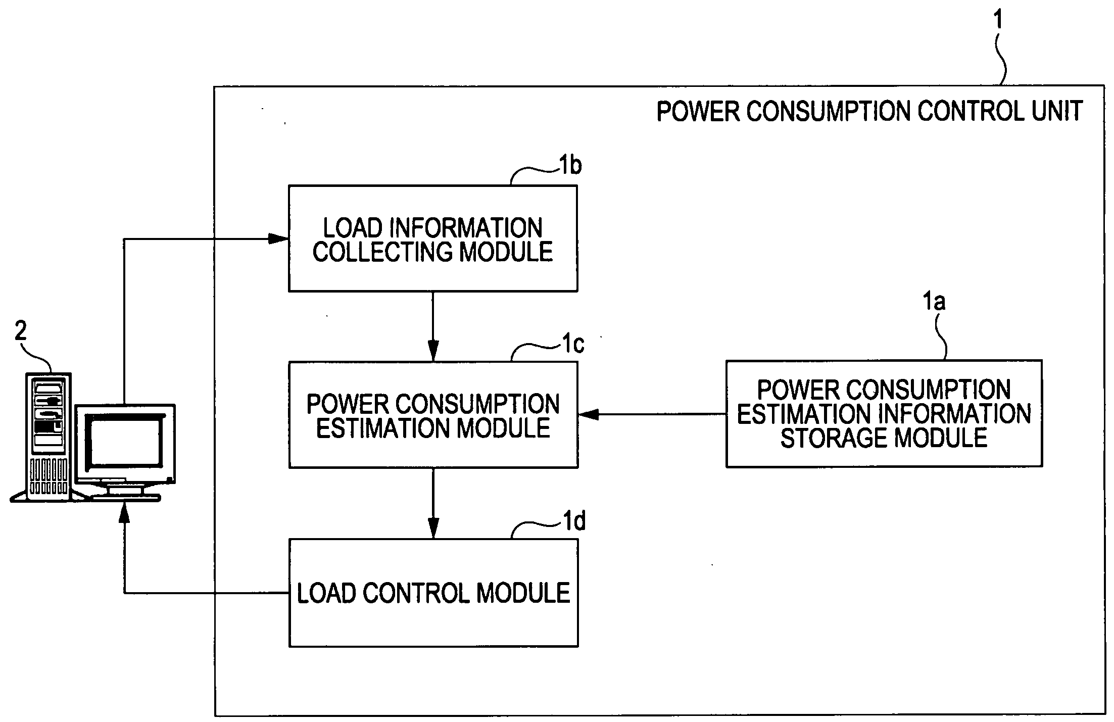
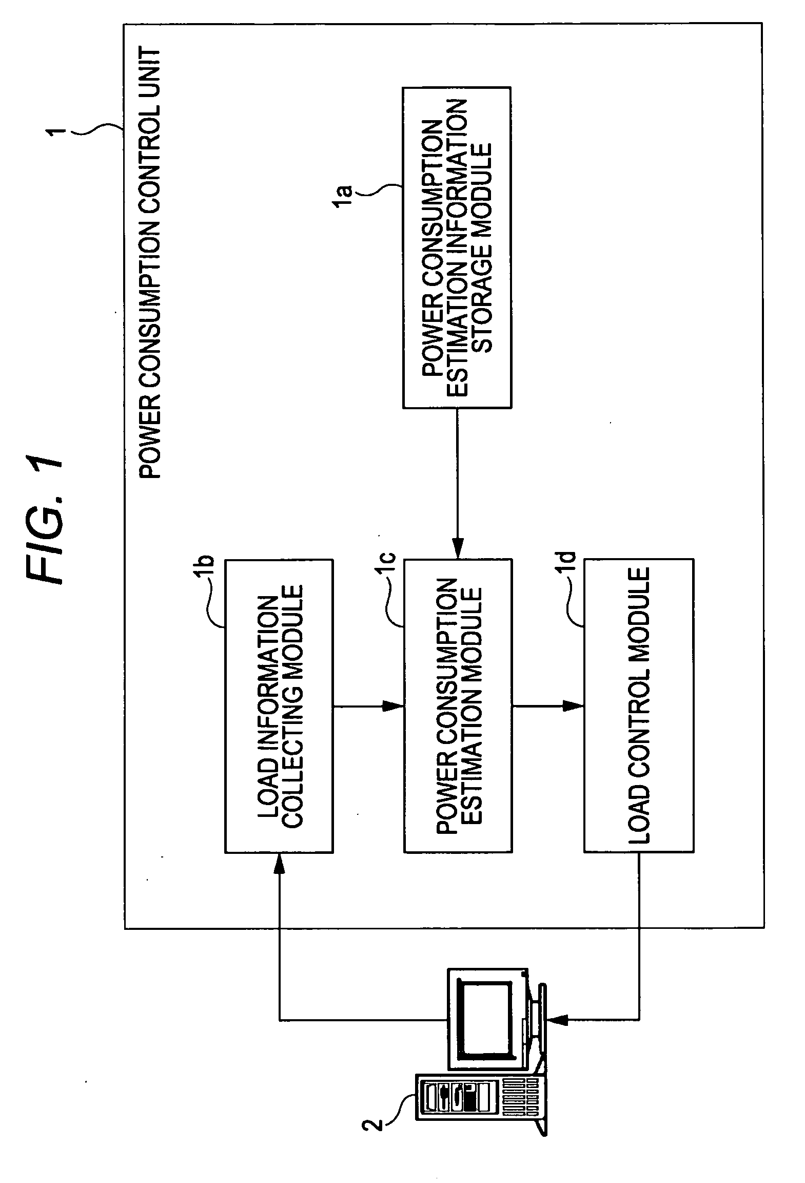
[0042]FIG. 1 depicts a system for monitoring and controlling power consumption of an electric device. Referring to FIG. 1, a power consumption control unit 1 includes a power consumption estimation information storage module 1a, a load information collecting module 1b, a power consumption estimation module 1c and a load control module 1d.

[0043]The power consumption estimation information storage module 1a stores power consumption estimation information indicating the power consumption corresponding to the processing load of an electric device 2. The power consumption estimation information storage module 1a sto...


PUM


Abstract

A power consumption monitor device monitors power consumption of one or more devices through a network. The monitor device includes a storage unit, a load information collecting unit and a power consumption estimation unit. The storage unit stores power consumption estimation information indicating a relation between power consumption and processing load of the one or more devices. The load information collecting unit collects load information indicating the processing load of the one or more devices through the network to the monitor device. The power consumption estimation unit estimates power consumption of the one or more device based on the collected load information and the power consumption estimation information.

Description

CROSS-REFERENCE TO RELATED APPLICATIONS[0001]This application claims the benefit of priority from Japanese Patent Application No. 2007-333970 filed on Dec. 26, 2007, which is herein incorporated by reference in its entirety.BACKGROUND[0002]1. Field[0003]Embodiments of the present invention relate to a method, device and computer-readable recording medium for monitoring the power consumption of one or more electronic devices.[0004]2. Description of Related Art[0005]The introduction of large-scale computer system generally requires power equipment sufficient to supply stable electric power to each electric device of the computer system. Each electric device may be supplied with power from a power distribution network arranged in a building installed with a computer system, for example. Each electric device may be connected to the power distribution network via a plug at the forward end of the power cable of each electric device. The plug may be inserted into the receptacle (plug socke...

Claims


Application Information

Patent Timeline
IPC IPC(8): G06F11/30G06F3/00G06F1/00
CPCG06F1/28G06F1/3203H02J3/14H02J2003/003Y04S10/54Y04S20/222Y04S10/30Y02E60/74Y02B70/3225H02J3/003H02J13/00002Y02E60/00H02J2310/60
Inventor OE, KAZUICHIKUMANO, TATSUONOGUCHI, YASUOTSUCHIYA, YOSHIHIROOGIHARA, KAZUTAKATAMURA, MASAHISAMARUYAMA, TETSUTAROWATANABE, TAKASHIKAMOSHIDA, MINORUMIYAMOTO, SHIGEYUKI
Owner FUJITSU LTD
Learn More