Network monitoring program, network monitoring method, and network monitoring apparatus

a network monitoring and network monitoring technology, applied in the field of network monitoring programs, network monitoring methods, network monitoring apparatus, can solve the problems of complex network configurations, inability to judge network faults, and high difficulty in specifying the location and cause of network failures

Inactive Publication Date: 2005-06-30
FUJITSU LTD
View PDF3 Cites 71 Cited by
  • Summary
  • Abstract
  • Description
  • Claims
  • Application Information

AI Technical Summary

Problems solved by technology

Furthermore, efforts are being made to make apparatus on networks more intelligent, resulting in more complex network configurations.
However, there are many instances where a network fault cannot be judged based on the operating states of individual apparatus.
Consequently, specifying the location and cause of a network failure is a highly difficult task to carry out.
In addition, if the location and cause of a network failure cannot be found for a long period of time, then business activities of customers which rely on the network are suspended for a long time.
If the operation statistic information is in excess of the index value, then it is judged that a fault symptom has occurred.
However, though the technique disclosed in Japanese unexamined patent publication No. 2002-99469 can automatically detect a fault symptom, the location and cause of the fault have to be determined by the system administrator.
However, the conventional monitoring system is unable to automatically determine where a fault has occurred on a communication path from the source apparatus to the destination apparatus.
Consequently, it has been customary to spend an excessive period of time to perform a fault analysis.
Since it is more difficult for larger-scale systems to identify a fault location, increased periods of time required for a fault analysis have posed a problem.
Another element which has made it difficult to carry out a fault analysis is the complexity of functions in each apparatus.
However, the conventional monitoring system does not have a monitoring function for a transport layer level.
Though the conventional monitoring system has a monitoring function based on the monitoring function (ICMP (Internet Control Message Protocol) function) of network apparatus, the monitoring function does not depend on actual communication statuses, and the monitoring system may make a wrong decision.
It has thus been difficult to accurately detect a fault of these functions.

Method used


Image

  • Network monitoring program, network monitoring method, and network monitoring apparatus
  • Network monitoring program, network monitoring method, and network monitoring apparatus
  • Network monitoring program, network monitoring method, and network monitoring apparatus

Examples


fault example 1

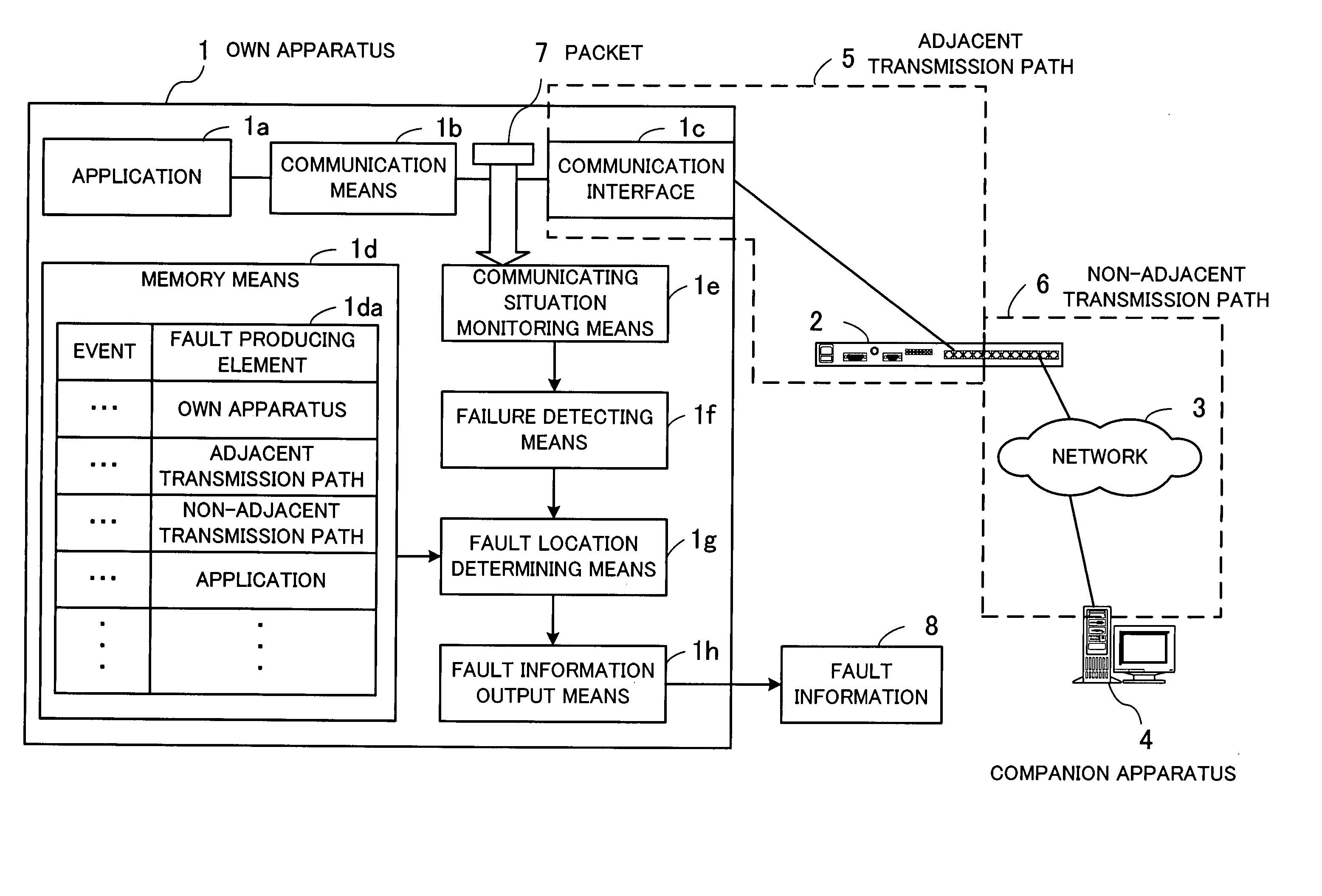
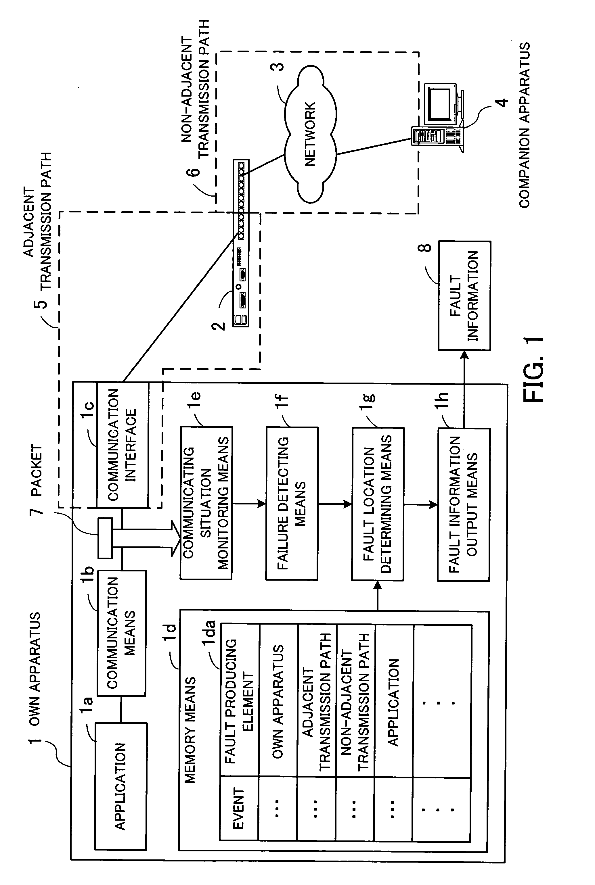
[0090] If the Ack response time of the own apparatus is longer than a reference value, then the connection monitor 130 detects a response delay. The fault determining unit 160 detects a fault based on the first record in the fault producing equipment classification table 151. At this time, since the “own apparatus” is registered as fault producing equipment in the record, the fault determining unit 160 judges that the own server is having some problem.

fault example 2

[0091] When all the connections with respect to the communication interfaces of the own server suffer a failure (a retransmitted packet, a duplicated received packet, lost data, or a response delay), the connection monitor 130 detects a connection failure. The fault determining unit 160 detects a fault based on the second record in the fault producing equipment classification table 151. At this time, since the “adjacent transmission path” is registered as fault producing equipment in the record, the fault determining unit 160 judges that the adjacent transmission path is having a failure.

fault example 3

[0092] If some connections are subjected to a failure at an unidentified IP address or port, then the connection monitor 130 detects such a connection failure. The fault determining unit 160 detects a fault based on the third record in the fault producing equipment classification table 151. At this time, since the “non-adjacent transmission path” is registered as fault producing equipment in the record, the fault determining unit 160 judges that an error has occurred in the non-adjacent transmission path.


PUM


Abstract

A network monitoring program automatically sorts fault producing locations on a network. A memory unit stores a fault location determining table containing events indicative of failures of communications via the network, the events being associated with classified elements which can be causes of faults on the network. A communication situation monitoring unit monitors communication situations with respect to other apparatus on the network. A failure detecting unit detects an event indicative of a failure from a communication situation detected by the communication situation monitoring unit. A fault location determining unit determines an element which is responsible for the event detected by the failure detecting unit by referring to the fault location determining table. A fault information output unit outputs fault information representative of a determined result from the fault location determining unit.

Description

BACKGROUND OF THE INVENTION [0001] (1) Field of the Invention [0002] The present invention relates to a network monitoring program, a network monitoring method, and a network monitoring apparatus for monitoring the operating state of a network, and more particularly to a network monitoring program, a network monitoring method, and a network monitoring apparatus for detecting a fault that has occurred on a network. [0003] (2) Description of the Related Art [0004] As the information technology develops, many business enterprises are making efforts to rely upon computer systems to perform their business activities efficiently. A computer system has a plurality of communication units such as computers, switches, etc. connected to each other by a network. Networks are becoming larger in scale year after year because of an increasing range of business activities that can be performed by computers. [0005] In view of attempts to make open and standardize system architectures, it has become ...

Claims


Application Information

Patent Timeline
Patent Type & Authority Applications(United States)
IPC IPC(8): G06F11/00G06F13/00G06F11/30H04B3/46H04L12/24
CPCH04L41/0631H04L41/0677H04L43/18H04L43/0852H04L43/10H04L43/0829
Inventor TAKEUCHI, SUSUMUSUZUKI, NORIHIKOSATO, ISAONAKATA, KEINAKANO, KENICHIKAMETANI, HIDEYUKINAKAJIMA, OSAMU
Owner FUJITSU LTD
Why Eureka
Try Eureka