
Method for determining the driving resistance of a motor vehicle

Inactive Publication Date: 2009-08-06
ZF FRIEDRICHSHAFEN AG
View PDF10 Cites 0 Cited by
  • Summary
  • Abstract
  • Description
  • Claims
  • Application Information

AI Technical Summary

Benefits of technology

[0037]Likewise, the actuation of decelerating devices, such as the working brakes, the parking brake or a retarder during the shift operation would lead to the determination of an erroneous extreme acceleration value (a_min or a_max) and thus also of an erroneous second driving resistance value F_fw—2, since the motor vehicle would then not be rolling freely during the traction-force-free phase. For example the working brakes, i.e., the wheel brakes, might be actuated either by the driver using the brake pedal or automatically by a control system such as ESP or ABS. To avoid an erroneous determination of the driving resistance F_fw caused by this, during the shift operation, it is expedient to detect the actuation status of the motor vehicle's decelerating devices and, if at least one of the decelerating devices is active, to discontinue the determination of the second driving resistance value (driving resistance during the shift operation) F_fw—2.

Problems solved by technology

Because of these problems, previous methods for controlling a transmission shift have not included any attempt to determine the driving resistance during a shift operation.
But if the driving resistance F_fw changes markedly during a shift, this can lead to problems, because the shift program of the transmission control unit begins from an erroneous driving resistance F_fw and the changed, correct driving resistance F_fw can only be determined after a time delay following the completion of the shift operation.
But if this downshift takes place too late, because of a delay in determining the new, higher driving resistance F_fw, in some circumstances the motor vehicle may come to rest if the drive engine torque, modified because of the gear engaged at the time, is no longer large enough to produce a sufficiently high traction force F_zug.

Method used


Image

  • Method for determining the driving resistance of a motor vehicle
  • Method for determining the driving resistance of a motor vehicle
  • Method for determining the driving resistance of a motor vehicle

Examples


Embodiment Construction

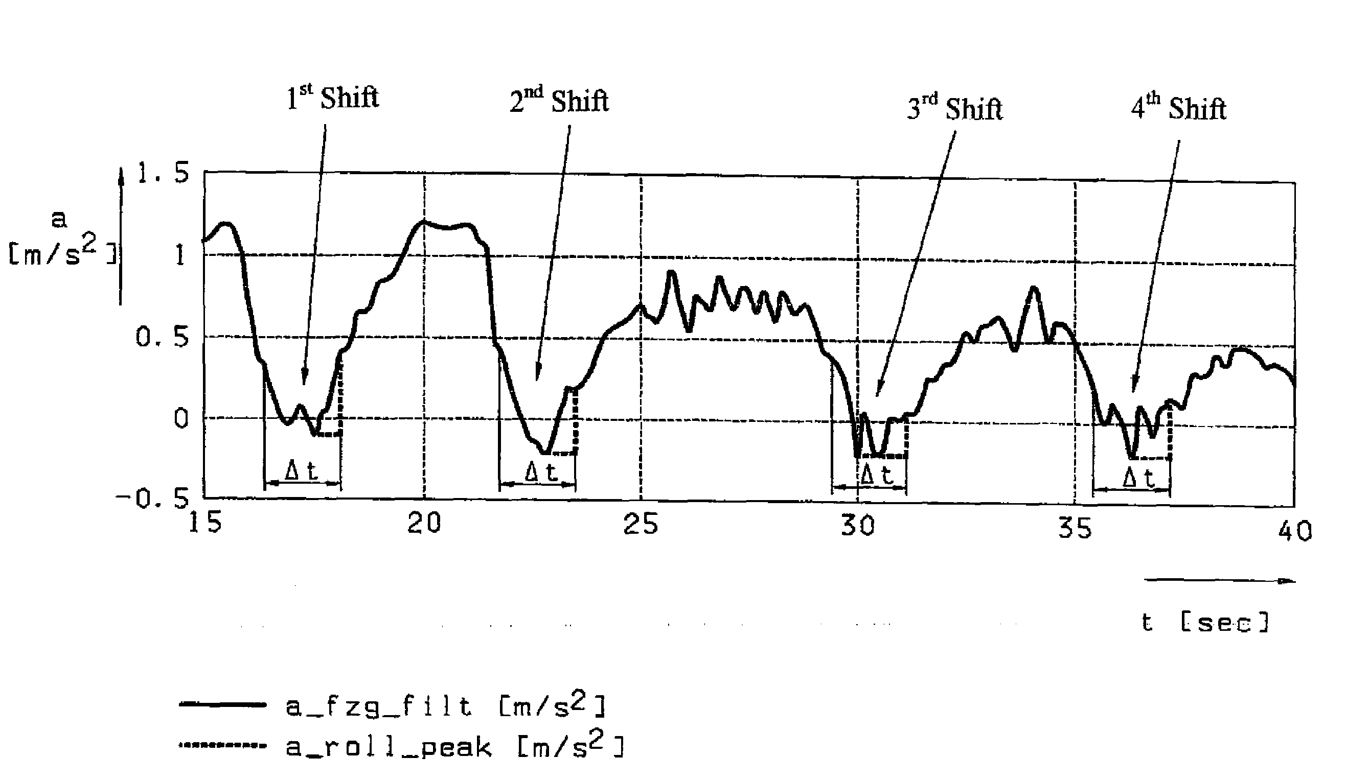
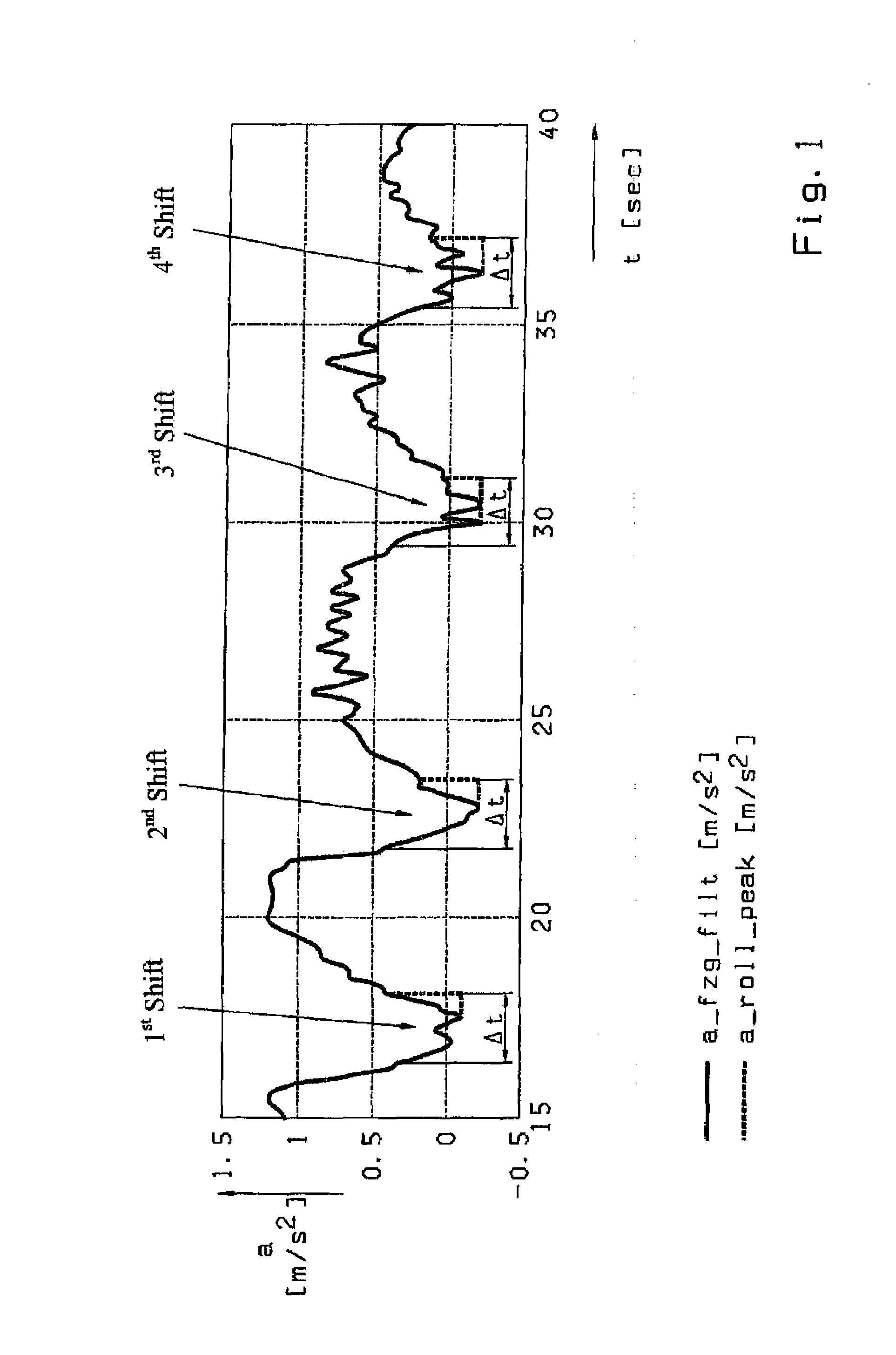
[0041]In the method, the determination of a change of the driving resistance F_fw during a gearshift operation relies on exact determination of a motor vehicle's acceleration a during the traction-force-free, rolling phase of the shift. An example of how this acceleration value is determined is illustrated in FIG. 1, which shows the time variation of the acceleration a of a motor vehicle over several shift operations, each involving an interruption of the traction force. In the Figure, the continuous line is a continuous representation of a filtered values a_fzg_filt, i.e., acceleration values a_i determined during a defined time interval of around 10 to 20 ms. Each of the shifts is a traction shift.

[0042]Consequently, each of the shifts results in a fall of the acceleration a, which assumes negative values 2 during the shift operations in each case. Thus, during each shift operation, the motor vehicle is slowed down by the effective driving resistance F_fit since the drive train is...


PUM


Abstract

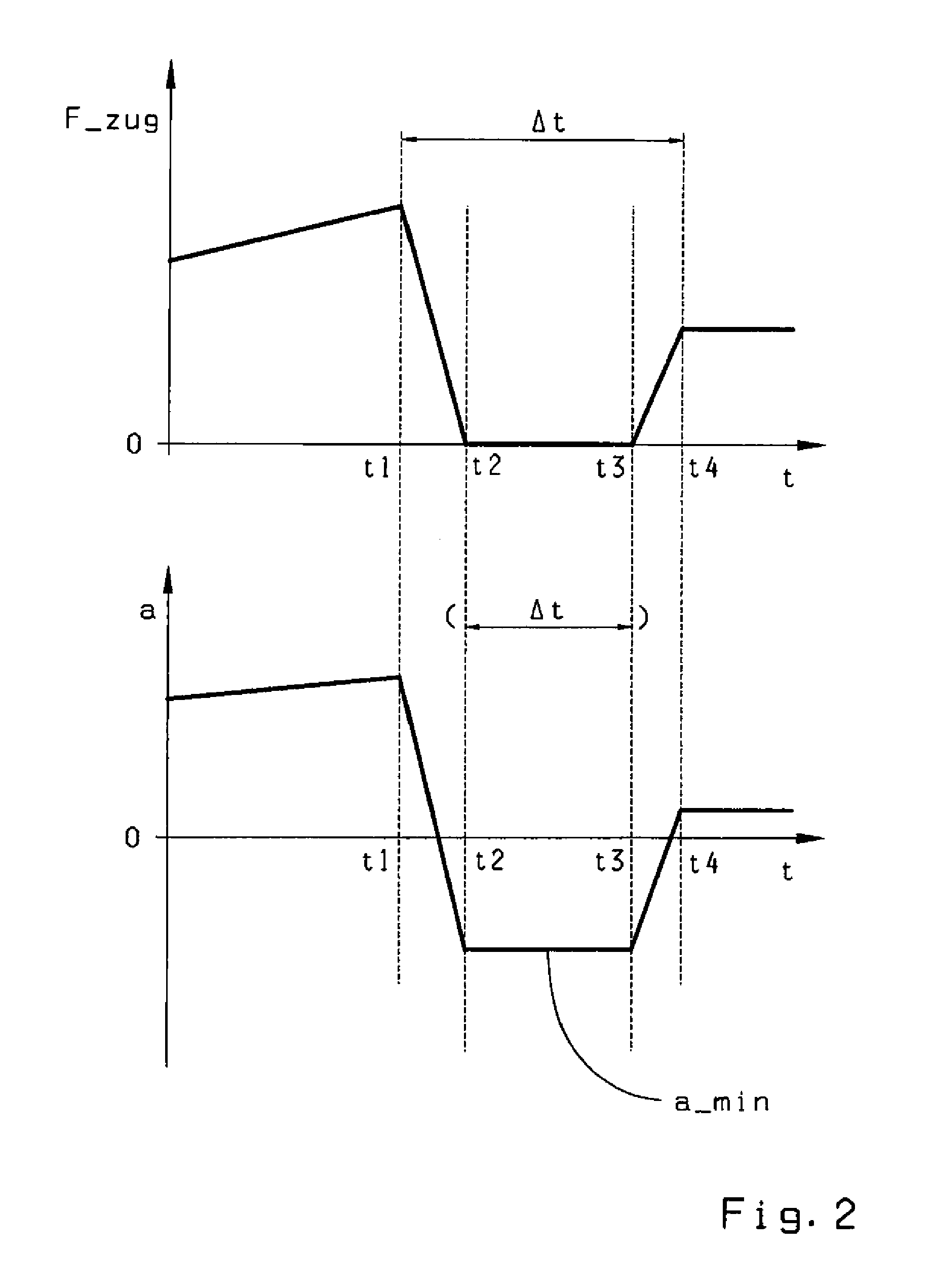
A method for determining the driving resistance of a motor vehicle simultaneously with a shift of an automated shift transmission from a load gear to a target gear such that if a difference between a first driving resistance value F_fw_1 and a second driving resistance value F_fw_2 is large, the shift operation can be corrected. The second driving resistance value F_fw_2 is determined during the shift operation. a time interval Δt which contains the traction-force-free phase of the shift, a plurality of acceleration values a_i of the motor vehicle are measured to obtain the minimum acceleration a_min if the shift operation is a traction shift or the maximum acceleration a_max if it is thrust shift. With the mass m of the vehicle, the second driving resistance value F_fw_2 is calculated with one of the formula F_fw_2=−m*a_min or F_fw_2=−m*a_max.

Description

[0001]This application is a national stage completion of PCT / EP2007 / 054014 filed Apr. 25, 2007, which claims priority from German Application Serial No. 10 2006 022 170.2 filed May 12, 2006.FIELD OF THE INVENTION[0002]The invention concerns a method for determining the driving resistance of a motor vehicle, which is implemented in conjunction with a shift of an automated shift transmission from a load gear to a target gear, such that a first driving resistance value F_fw—1 is determined before the shift operation begins and a second driving resistance value F_fw—2 is determined at a later point in time, so that, if the change of the driving resistance ΔF_fw =F_fw—2−F_fw—1 is large, the shift operation can be corrected.BACKGROUND OF THE INVENTION[0003]Knowledge of the driving resistance of a motor vehicle is of fundamental importance in enabling optimum control of the shifting behavior of an automated shift transmission, i.e., control which is adapted to the driving situation at the ...

Claims


Application Information

Patent Timeline
IPC IPC(8): F16H61/02
CPCF16H59/14F16H2059/142F16H61/0213
Inventor WOLFGANG, WERNERWURTHNER, MAIKSAUTER, INGO
Owner ZF FRIEDRICHSHAFEN AG
Learn More