Manual Thickness Measurement Gage

Inactive Publication Date: 2013-03-21
HUSTED ERNIE
View PDF13 Cites 17 Cited by
  • Summary
  • Abstract
  • Description
  • Claims
  • Application Information

AI Technical Summary

Benefits of technology

[0006]In another aspect of the apparatus, a spring is used to press one contactor toward the other thereby eliminating the variability of manual pressure.
[0007]In another aspect of the apparatus, the pressure

Problems solved by technology

The measuring accuracy is affected as well by distortion of the specimen caused by the contacts.
Clearly, the use of such a tool has disadvantages as well.
For example accuracy may suffer due to changes in ambient temperature within a factory site over the course of a work shift.
Dust particles ma

Method used


Image

  • Manual Thickness Measurement Gage
  • Manual Thickness Measurement Gage
  • Manual Thickness Measurement Gage

Examples


Example

[0017]Like reference symbols in the drawings indicate like elements.

DETAILED DESCRIPTION

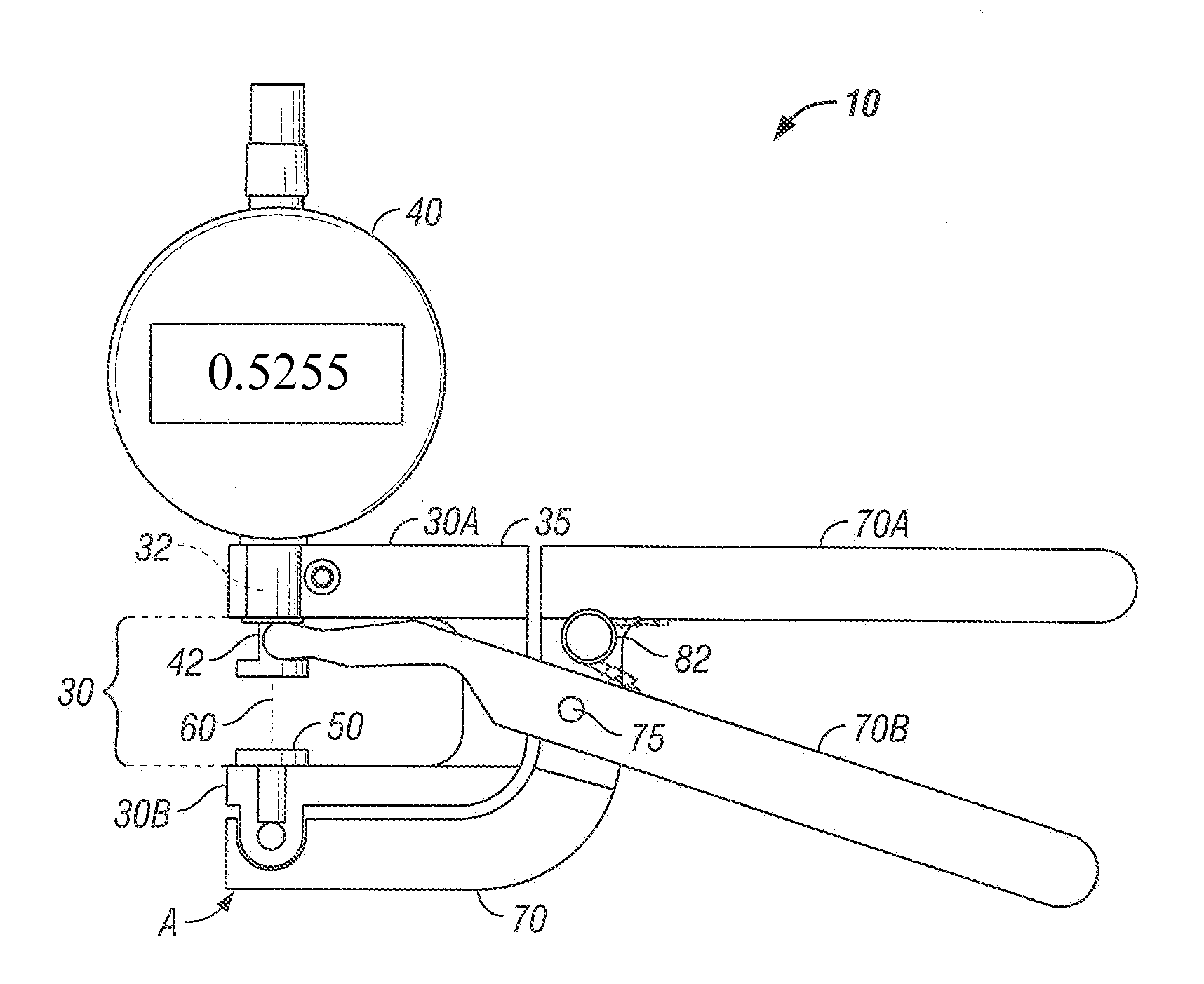
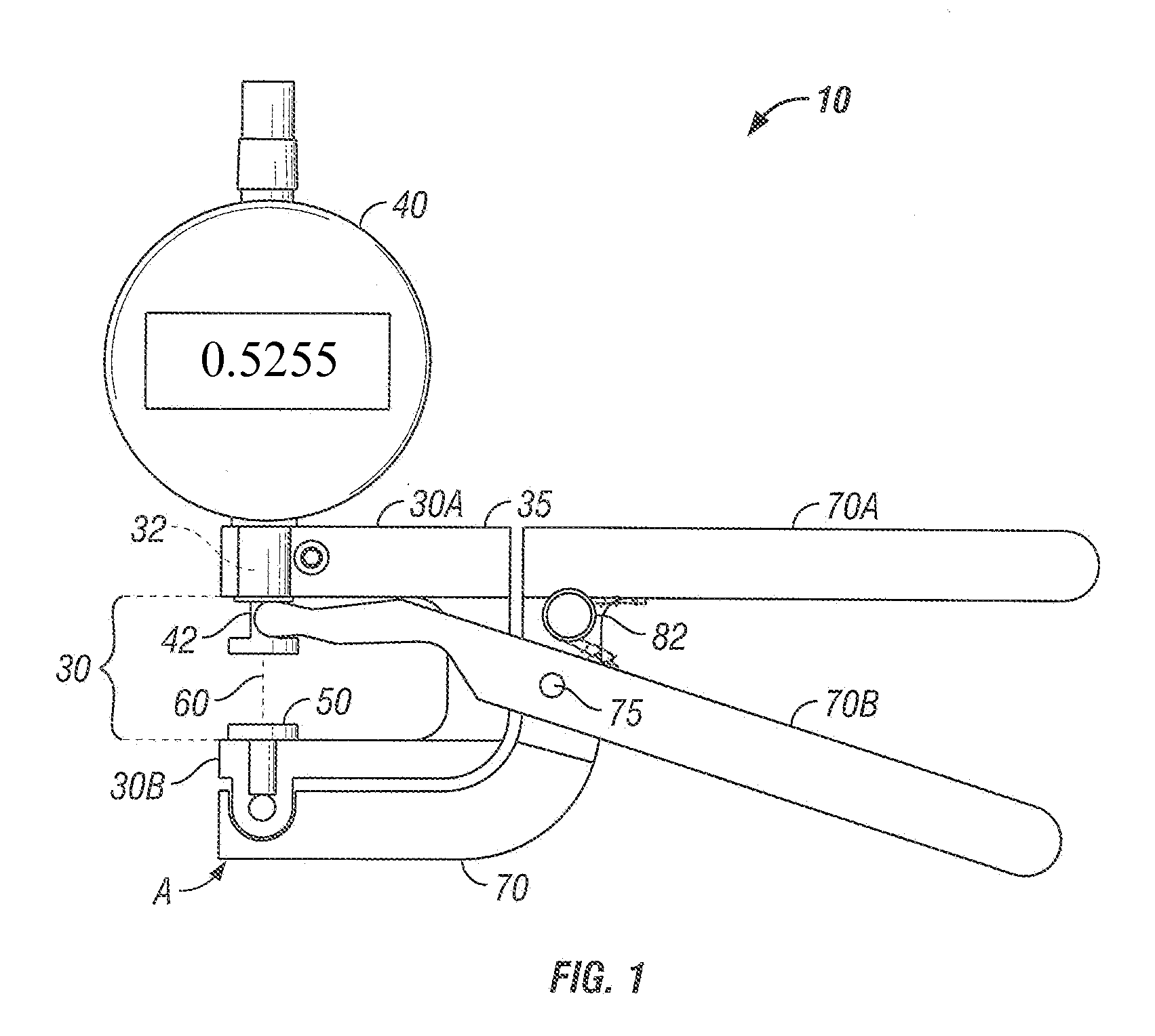
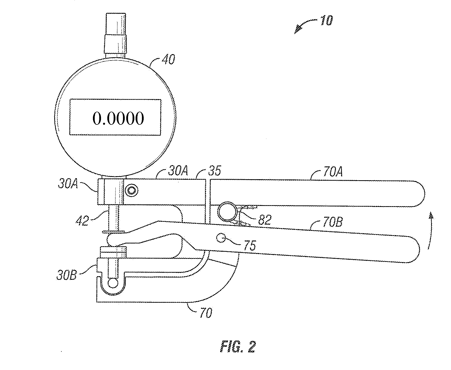
[0018]The figures illustrate a manual thickness measuring tool 10, the subject of this disclosure. The tool 10 is used for measuring the thickness of a sheet material workpiece 20, as shown in FIGS. 3 and 5. As shown, a top 30A and a bottom 30B jaws form a rigid C-frame 35 defining a space 30 between the jaws. A measurement gauge 40 is supported on the top jaw, and a workpiece rest 50 is supported on the bottom jaw 308. A measurement probe 42 is operationally engaged with the measurement gauge 40 wherein linear extension of the probe 42 along a line of travel 60 in the space 30 derives linear measurement by the is measurement gauge 40. The probe 42 is joined with gauge 40 through a clearance hole 32 in the top jaw 30A. The relationship between gauge 40 and probe 42 is not described here as this device is very well known in the field of calibration and measurement metrology. A handle assembly 70 i...


PUM


Abstract

A manual gauge measures a specimen's thickness by pressing surface contactors against its opposing surfaces. A rigid C-frame has upper and lower jaws providing a means for engaging a specimen and for gauging its thickness using a linear probe that is caused to move linearly between the jaws by a handle assembly. The handle assembly is joined with the C-frame at a point that is co-linear with a force vector of the probe against a workpiece resting on one of the jaws. The force of the probe is transmitted through the specimen to the jaw. The handle leverages from this jaw so that there is no force applied between the jaws thereby avoiding error due to the varying hand pressure by the operator and the resultant strain in the C-frame during measurements.

Description

BACKGROUND[0001]The present disclosure relates to hand gauges for measuring material thickness and more particularly to such a hand operated gauge capable of more precise measurements and particularly a hand operated thickness measuring gauge capable of avoiding error due to the differences in applied hand pressure of different operators.[0002]Contact measuring tools are widely used to measure the thickness of flat materials by utilizing a linear gauge or the like. When measurements involve simultaneously contacting opposing sides of material (specimen) and determining the thickness thereof, conventional tools are used such as are described in US patents: U.S. Pat. Nos. 202,866; 346,706; 2,051,357; 2,080,534; 2,152,880; 2,734,275; and 3,208,148. in common use are gauges that use a C-shaped jaw having a fixed jaw opening and which have a fixed handle mounted as a part of the jaw, and a pivoting handle also mounted to the jaw allowing the two handles to be squeezed toward each other t...

Claims


Application Information

Patent Timeline
IPC IPC(8): G01B5/06
CPCG01B3/24G01B5/06
Inventor HUSTED, ERNIE
Owner HUSTED ERNIE
Why Eureka
Try Eureka