Motor vehicle spring comprising fiber composite material

a composite material and motor vehicle technology, applied in the field of motors, can solve problems such as disadvantages high, and achieve the effects of reducing costs, reducing costs, and reducing widths

Inactive Publication Date: 2009-08-13
MUHR UND BENNDER KG
View PDF12 Cites 20 Cited by
  • Summary
  • Abstract
  • Description
  • Claims
  • Application Information

AI Technical Summary

Benefits of technology

[0016]Both the variation in the width of the spring band and the variation in the thickness of the spring band is preferable provided to be substantially continuous or finely stepped. The variation in the width can be provided through modifying the shape of the cut of the prepregs. In addition, the variation in the thickness can be effected by providing portions having larger numbers of prepreg layers.
[0017]Additional advantages of material utilisation and cost reduction, can be achieved in an embodiment of a band spring, according to the invention having several layers, with a central layer comprising prepregs of a lower quality, such as glass-fiber-reinforced resin-impregnated material, and outer layers comprising prepregs of a higher quality, such as a carbon-fiber-reinforced or aramid-fiber-reinforced resin-impregnated material.

Problems solved by technology

Compression is effected through deformation of the respective second reversal regions having thinner material and which, can be subjected to disadvantageously high loads as a consequence.

Method used


Image

  • Motor vehicle spring comprising fiber composite material
  • Motor vehicle spring comprising fiber composite material
  • Motor vehicle spring comprising fiber composite material

Examples


first embodiment

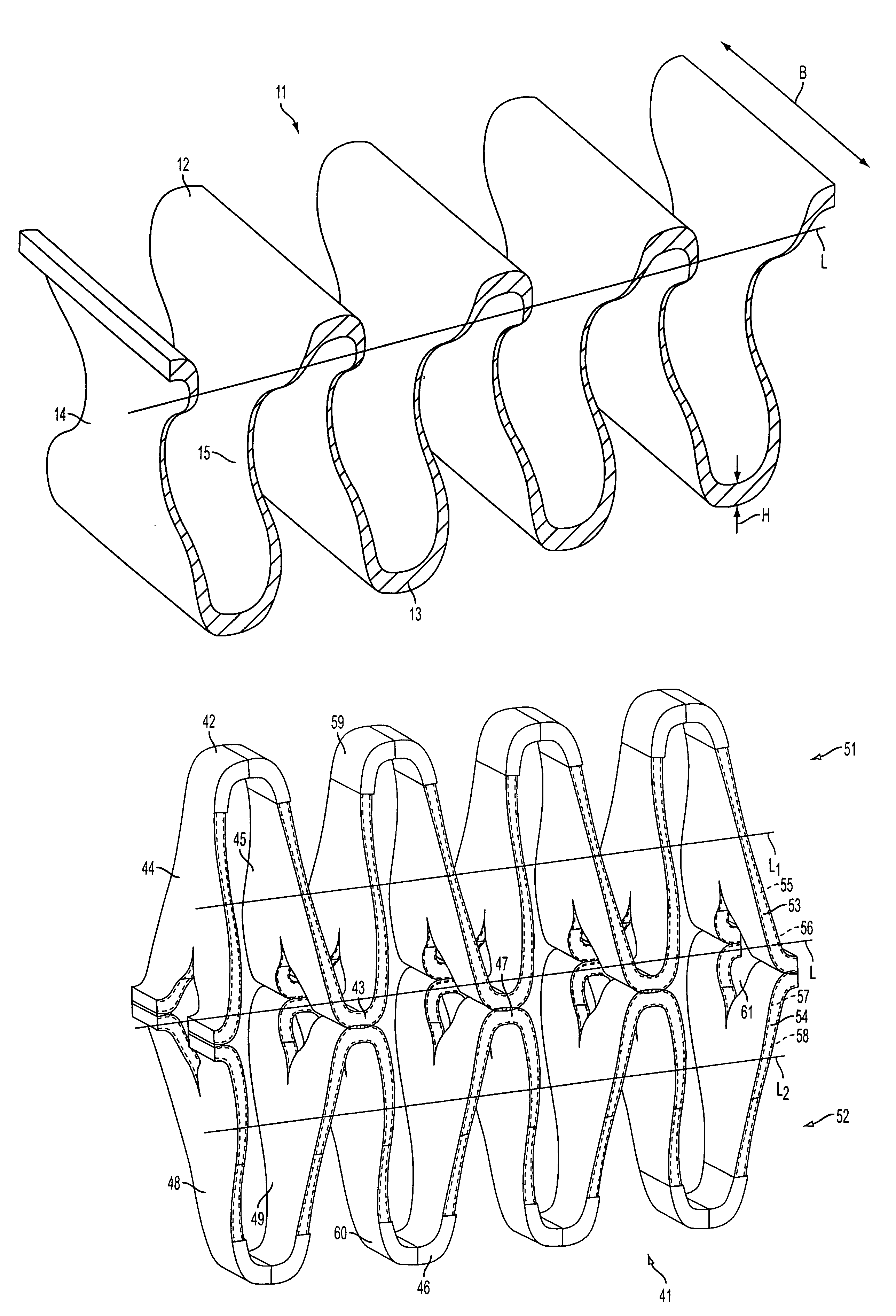
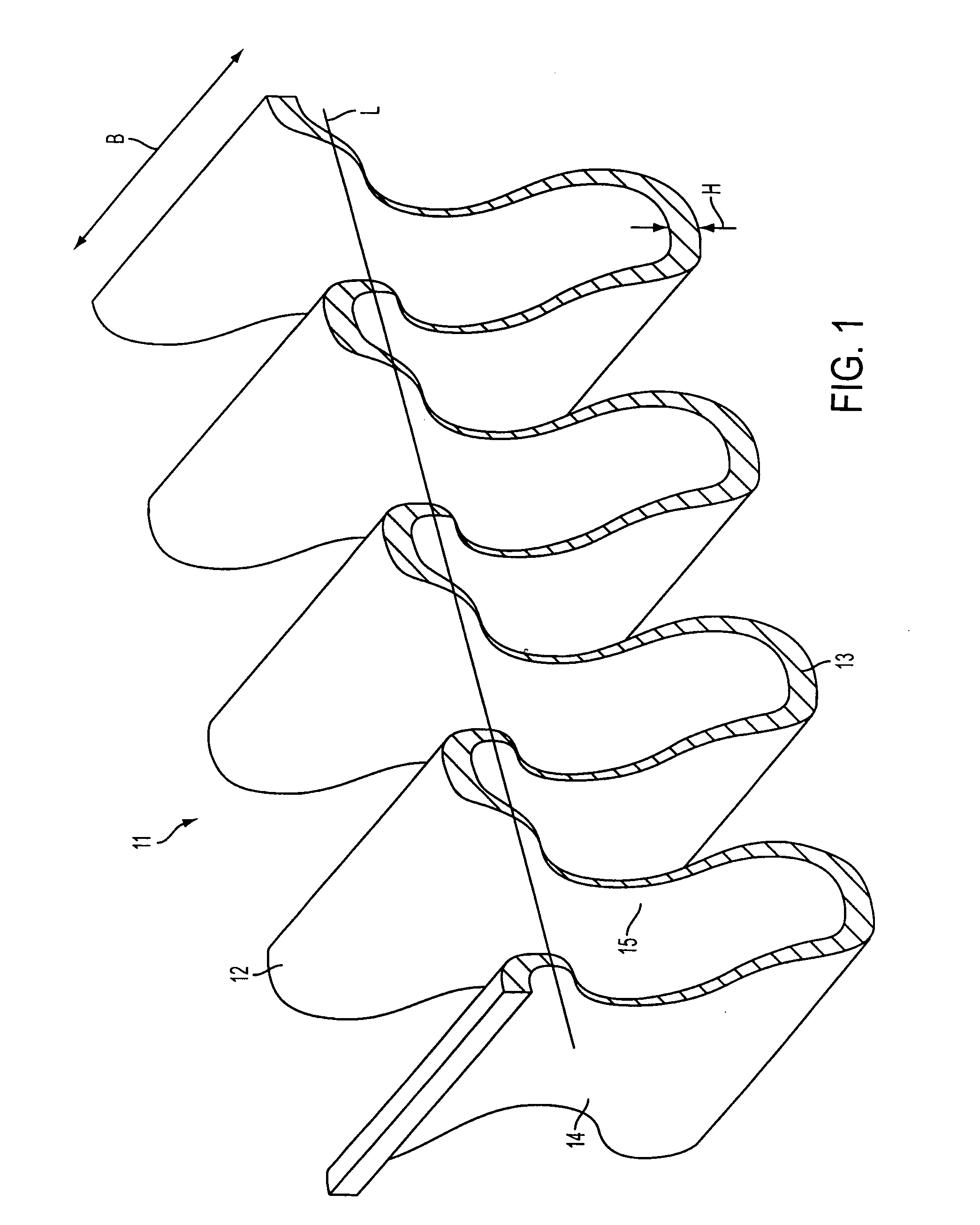
[0047]FIG. 1 shows an inventive band spring 11 in a first embodiment which comprises a wave-shaped spring band, and which can be provided to meander around a longitudinal center line L to form four complete wave units. Three complete first reversal regions 12, and two halves of first reversal region 12, are provided. In addition, four complete second reversal regions 13, with the two halves of reversal regions are also provided, defining the ends of the band spring 11. The more strongly curved reversal regions 12, 13 can be connected by intermediate regions 14, 15 having a less pronounced curvature. In the present embodiment, the material thickness of the spring band can be variable, and the thickness H and the spring band width B, which extends transversely to the wave line, can be provided to be much greater in the reversal regions 12, 13 than in the connecting regions14, 15. The changes in width can be provided to be at a constant rate, and can be provided in a form represented b...

second embodiment

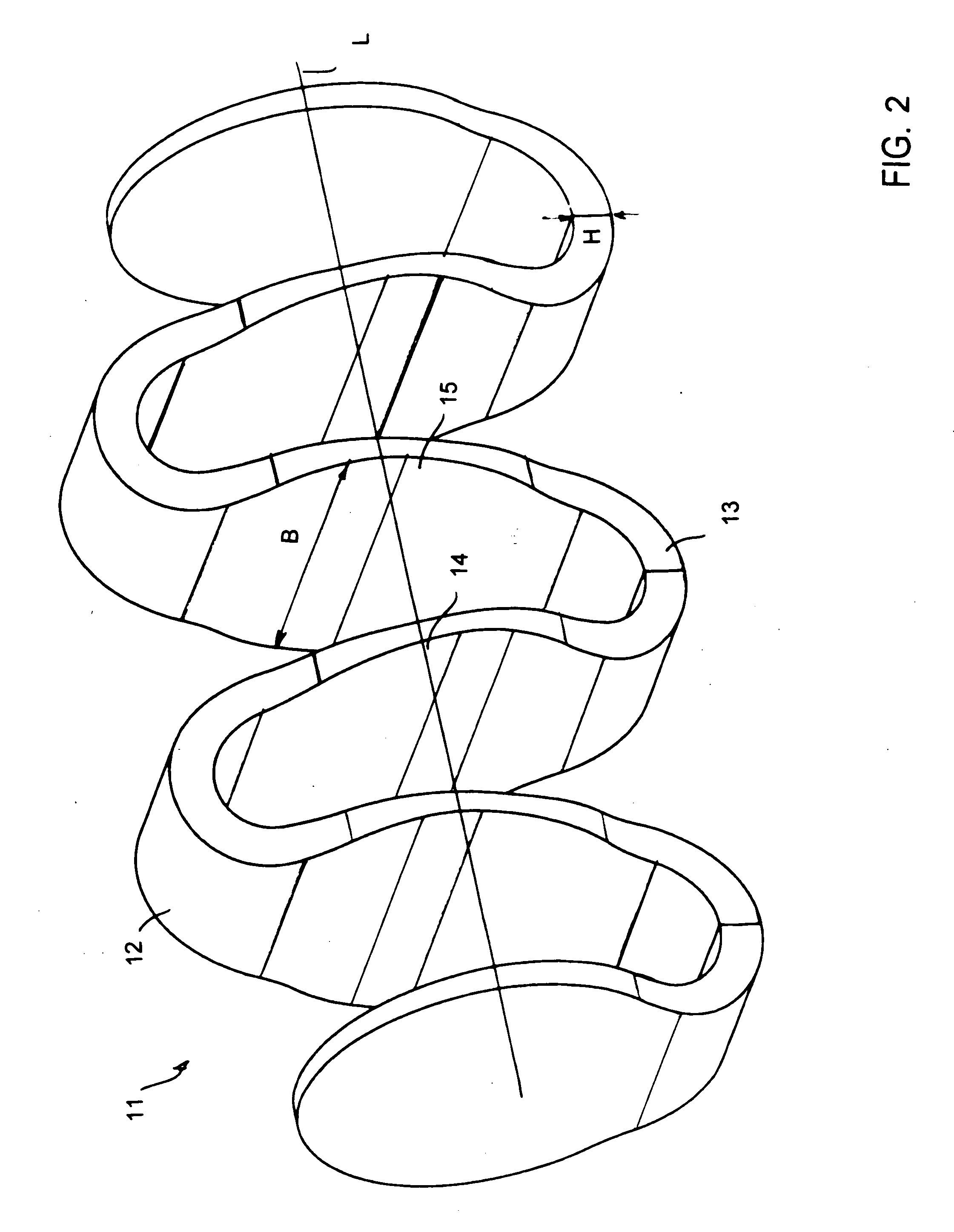
[0048]FIG. 2 shows an inventive band spring 11 in a second embodiment which comprises a wave-shaped spring band and which can be provided to meander around a longitudinal center line L to form two complete wave units. Two complete first reversal regions 12, and three complete second reversal regions 13 are provided. In addition, the ends of the band spring 11 can be provided so that they do not form reversal regions. The more strongly curved reversal regions 12, 13 can be connected by intermediate portions 14, 15 with a lesser curvature. In the present embodiment, the material thickness of the spring band can be variable, and the thickness H in the reversal regions 12, 13 can be provided to be greater. The width B of the band string in the reversal regions 12, 13, which width B extends transversely to the wave line, can be provided to be smaller than in the connecting regions 14, 15. The changes in width can be provided to be at a constant rate and can be provided in a form represen...

third embodiment

[0049]FIG. 3 shows a band spring 21 in a Identical details have been given the same reference numbers in as the case of the band spring according to FIG. 1. To that extent, reference is made to the preceding description. The band spring 21 shown here comprises one spring band which can be provided to meander around a longitudinal center line L to form a total of four complete wave units. The thickness H of the spring band can be constant, and the width B of the spring band can be provided to vary. The reversal regions 12, 13 can be provided to have a greater width relative to the intermediate portions 14, 15. Among other things, FIG. 3 deviates from FIG. 1, in that the intermediate portions 14, 15 can comprise holes 16 whose centers (not especially marked) can be positioned on the longitudinal center line L and whose sizes can correspond to one another, so that, if viewed in the direction of the longitudinal center line L, the holes 16 can be aligned relative to one another. It can...


PUM


Abstract

A band spring including fiber composite material and extending in an undulating way, wherein a spring band can be provided to meander in the form of one single wave train composed of reversal regions and intermediate portions around a longitudinal center line L which can substantially correspond to the direction of force introduction K, and wherein, there can be provided an increased resistance moment of the spring band in the reversal regions of the wave train.

Description

SUMMARY[0001]The invention relates to a band spring comprising a fiber composite material extending in an undulating way, wherein a spring band meanders in the form of one single wave train having reversal regions and intermediate portions around a longitudinal center line L which, substantially, corresponds to the direction of a force being introduced K.[0002]Furthermore, the invention relates to a band spring comprising a fiber composite material and extending in a double wave form, wherein two spring bands meander in the form of wave trains having reversal regions and intermediate portions around two center lines L1, L2 which extend parallel relative to one another and which are positioned parallel to a longitudinal center line L which is positioned therebetween and which substantially corresponds to the direction of a force being introduced K.BACKGROUND[0003]Products comprising fiber composite materials can be produced from mattings of resin-impregnated woven fabrics or fiber ma...

Claims


Application Information

Patent Timeline
Patent Type & Authority Applications(United States)
IPC IPC(8): F16F1/02
CPCB60G11/00B60G15/062B60G2202/11B60G2202/116B60G2202/14F16F15/022B60G2206/42B60G2206/428B60G2206/7101F16F1/027B60G2202/141
Inventor KOBELEV, VLADIMIRWESTERHOFF, KARSTENNEUBRAND, JORGBRANDT, ROBERTBRECHT, JORG DIETER
Owner MUHR UND BENNDER KG
Why Eureka
Try Eureka