Method for manufacturing vehicle wheel

a manufacturing method and technology for vehicles, applied in the direction of vehicle components, brake types, rolling resistance optimization, etc., can solve problems such as appearance likely to deteriorate, and achieve the effect of high design property and good appearan

Active Publication Date: 2022-09-15
CENTRAL MOTOR WHEEL CO LTD
View PDF6 Cites 0 Cited by
  • Summary
  • Abstract
  • Description
  • Claims
  • Application Information

AI Technical Summary

Benefits of technology

The invention describes a new method for making vehicle wheels that have a high design property (a good appearance). This method is different from existing methods. By using this method, a bright surface can be formed that is linearly extended along the edge of the cut surface and the surface of the workpiece, making the wheel visually emphasized. The method also reduces the variation in the width of the bright surface by chamfering the edge using machining, as compared to manual chamfering.

Problems solved by technology

Since the bright surface formed in the chamfering step in the method for manufacturing the vehicle wheel extends linearly, the appearance is likely to deteriorate when the width of the bright surface varies greatly.

Method used


Image

  • Method for manufacturing vehicle wheel
  • Method for manufacturing vehicle wheel
  • Method for manufacturing vehicle wheel

Examples


first embodiment

[0019]A. First Embodiment

[0020]A-1. Structure of Vehicle Wheel 100

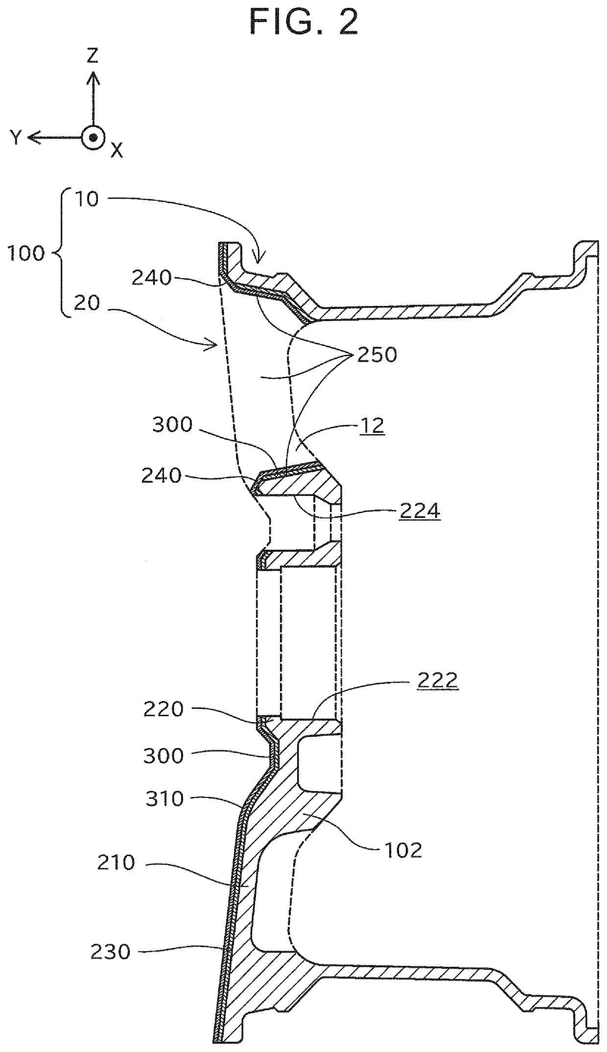
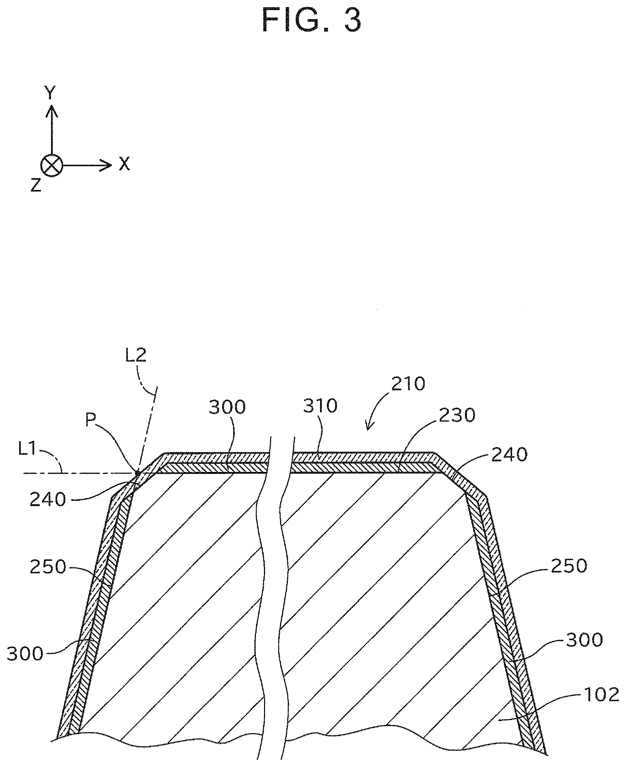
[0021]FIG. 1 is an XZ plan schematically illustrating the external structure of a vehicle wheel 100 (hereinafter referred to simply as “wheel 100”) according to a first embodiment. FIG. 2 is an explanatory drawing schematically illustrating a YZ sectional structure of the wheel 100. FIG. 2 illustrates a YZ sectional structure of the wheel 100 at a position II-II in FIG. 1. FIG. 3 is an explanatory drawing schematically illustrating an XY sectional structure of the wheel 100 according to this embodiment. FIG. 3 illustrates an XY sectional structure of a spoke 210 of the wheel 100 at a position III-III in FIG. 1. In the drawings, X, Y, and Z axes orthogonal to each other are illustrated to determine directions. For convenience, a Y-axis direction is herein parallel to a rotational axis of the wheel 100, and is hereinafter referred to as “wheel axial direction”. In actuality, the wheel 100 may be disposed in a direction ...

second embodiment

[0043]B. Second Embodiment

[0044]FIG. 6 is an XZ plan schematically illustrating the external structure of a part of a wheel 100a according to a second embodiment. FIG. 7 is an explanatory drawing schematically illustrating a YZ sectional structure of the wheel 100a. FIG. 7 illustrates a YZ sectional structure of the wheel 100a at a position VII-VII in FIG. 6. Among components of the wheel 100a of the second embodiment, components identical to the components of the wheel 100 of the first embodiment are represented by the same reference symbols to omit their description as appropriate.

[0045]In the first embodiment, the shape of the bright surface 240 formed on the wheel 100 is a substantially triangular loop shape when viewed in the wheel axial direction. In the second embodiment, the shape of a bright surface 240a formed on the wheel 100a is a partially discontinuous non-loop shape when viewed in the wheel axial direction.

[0046]Specifically, as illustrated in FIG. 6, the shape of the...


PUM


Abstract

A method for manufacturing a vehicle wheel is a method for manufacturing a vehicle wheel including a wheel rim having a substantially cylindrical shape and a wheel disc provided on an inner peripheral side of the wheel rim. The method includes forming a workpiece of the vehicle wheel by casting or forging, the workpiece being a light metal workpiece; cutting a part of the workpiece to form a cut surface; coating, with a colored paint, the cut surface, an edge where the cut surface intersects a surface of the workpiece, and at least a portion around the edge in the surface of the workpiece; and chamfering the edge to form a bright surface where the workpiece is exposed, after coating the cut surface, the edge, and at least the portion around the edge.

Description

CROSS-REFERENCE TO RELATED APPLICATION[0001]This application claims priority to Japanese Patent Application No. 2021-037394 filed on Mar. 9, 2021, incorporated herein by reference in its entirety.BACKGROUND1. Technical Field[0002]The technology described in the disclosure relates to a method for manufacturing a vehicle wheel.2. Description of Related Art[0003]There is known a method for manufacturing a vehicle wheel in which a bright surface where a metal workpiece is exposed is formed by machining, on a lathe, the surface of a coated light metal wheel together with a coated film to enhance a design property. Since the bright surface is formed by machining on the lathe, the bright surface can be provided only at an outermost part of the vehicle wheel. Therefore, the bright surface is a simple flat surface or a simple curved surface. A method for manufacturing a vehicle wheel having a bright surface in a more complex shape is disclosed in, for example, each of Japanese Unexamined Pat...

Claims


Application Information

Patent Timeline
IPC IPC(8): B21D53/34
CPCB21D53/34B23P15/00B23P2700/50Y02T10/86
Inventor TAKASHIMA, EIJI
Owner CENTRAL MOTOR WHEEL CO LTD
Why Eureka
Try Eureka