Method and apparatus for distributed var compensation

a distributed and var technology, applied in the field of voltampere reactive (var) compensation, can solve the problems of increasing the difficulty of obtaining building permits to expand on this capacity, the pressure to utilize the existing infrastructure to its maximum, and the power level of the commercial power grid is nearing the maximum capacity

Active Publication Date: 2009-08-13
ENPHASE ENERGY
View PDF9 Cites 103 Cited by
  • Summary
  • Abstract
  • Description
  • Claims
  • Application Information

AI Technical Summary

Benefits of technology

[0011]Embodiments of the present invention relate to a method and apparatus for generating on-demand power. The method comprises receiving a peak reactive current request, generating a control signal based on the peak reactive current request, and utilizing the control signal to drive a DC / AC inverter to generate the reactive power commensurate with the peak reactive current request.

Problems solved by technology

Due to such increased usage, power levels on the commercial power grid are nearing the maximum capacity of the grid, and building permits to expand on this capacity are becoming more difficult to obtain.
The pressure to utilize the existing infrastructure to its maximum is therefore extreme.
These reactive currents create many challenges for the utilities, including inducing spurious losses on the lines and the generators, creating stability problems, and affecting the grid voltage.
Utilities do not charge for reactive power but can suffer greatly from its consequences.
However, existing standards for distributed generators (DGs) usually prohibit the DG from generating reactive currents, leaving the utility to only see the reactive part of the load if the DG is offsetting the real load.

Method used


Image

  • Method and apparatus for distributed var compensation
  • Method and apparatus for distributed var compensation
  • Method and apparatus for distributed var compensation

Examples


Embodiment Construction

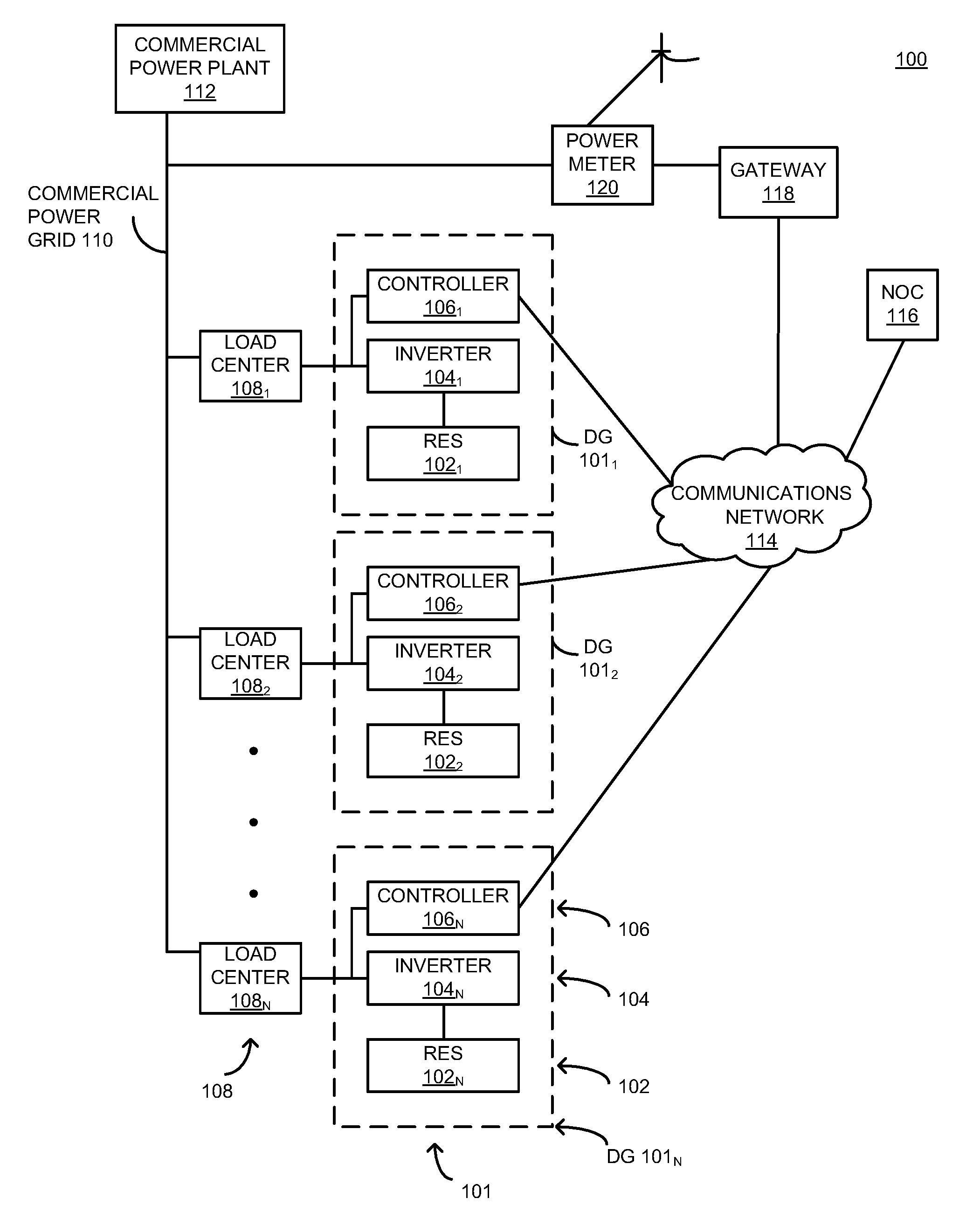
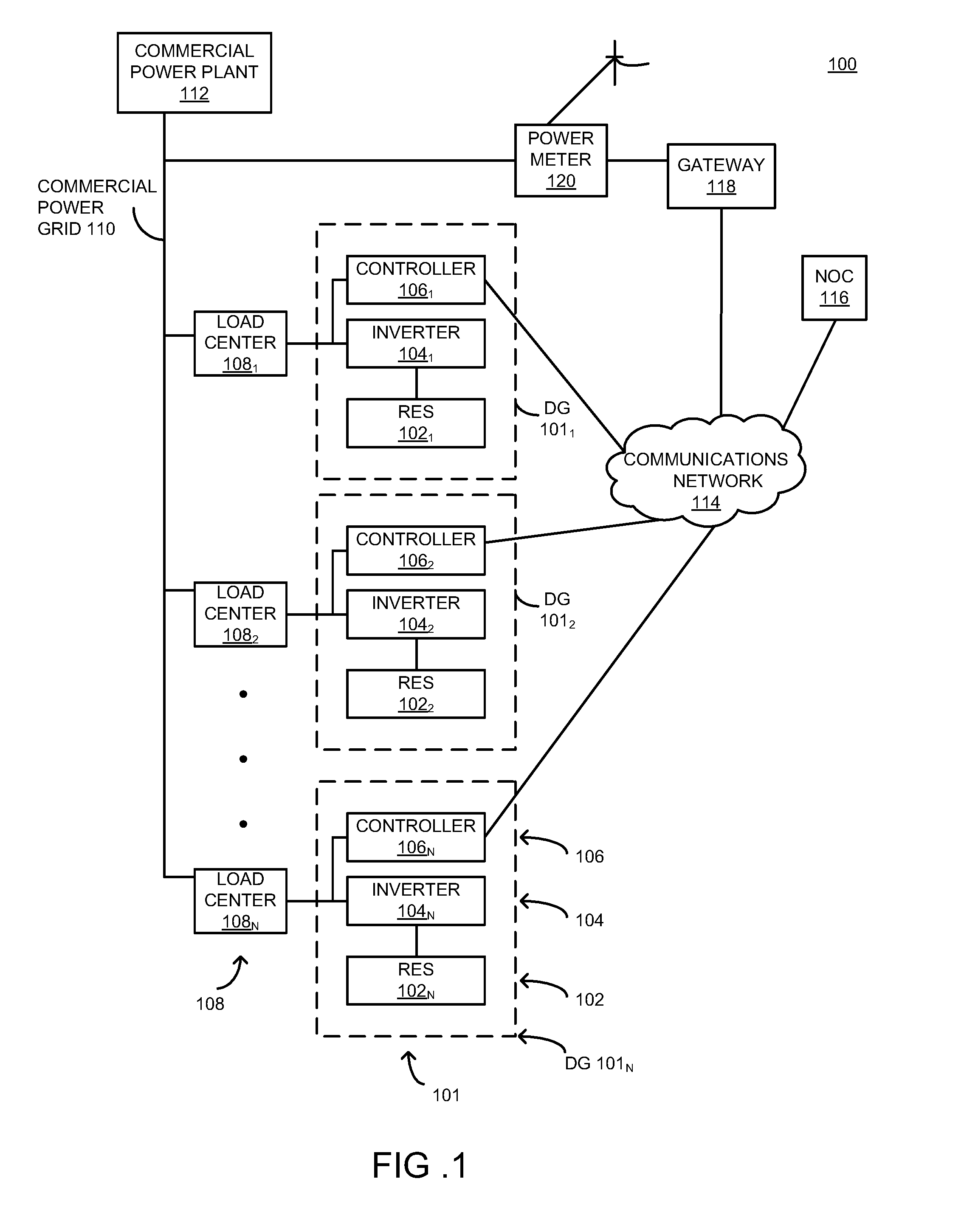
[0020]FIG. 1 is a block diagram of a distributed generator (DG) system 100 for generating on-demand VAr compensation in accordance with one or more embodiments of the present invention. This diagram only portrays one variation of the myriad of possible system configurations. The present invention can function in a variety of distributed power generation environments and systems.

[0021]The DG system 100 comprises a plurality of renewable energy sources (RES) 1021, 1022 . . . 102n, collectively referred to as RESs 102, a plurality of inverters 1041, 1042 . . . 104n, collectively referred to as inverters 104, a plurality of controllers 1061, 1062 . . . 106n, collectively referred to as controllers 106, and a plurality of load centers 1081, 1082 . . . 108n, collectively referred to as load centers 108.

[0022]Each RES 1021, 1022 . . . 102n is coupled to an inverter 1041, 1042 . . . 104n, respectively, and each inverter 1041, 1042 . . . 104n is further coupled to a controller 1061, 1062 . ....


PUM


Abstract

A method and apparatus for generating on-demand power. The method comprises receiving a peak reactive current request, generating a control signal based on the peak reactive current request, and utilizing the control signal to drive a DC/AC inverter to generate reactive power commensurate with the peak reactive current request.

Description

CROSS-REFERENCE TO RELATED APPLICATIONS[0001]This application claims benefit of U.S. provisional patent application Ser. No. 61 / 065,463, filed Feb. 12, 2008, which is herein incorporated in its entirety by reference.BACKGROUND OF THE INVENTION[0002]1. Field of the Invention[0003]Embodiments of the present disclosure generally relate to Volt-Ampere reactive (VAr) compensation and, more particularly, to a method and apparatus for generating on-demand VAr compensation.[0004]2. Description of the Related Art[0005]Current worldwide growth in demand for electricity is leading to a durable increase in energy usage. Due to such increased usage, power levels on the commercial power grid are nearing the maximum capacity of the grid, and building permits to expand on this capacity are becoming more difficult to obtain. The pressure to utilize the existing infrastructure to its maximum is therefore extreme.[0006]Demand Response (DR) is a well-established business model used by utilities to incr...

Claims


Application Information

Patent Timeline
Patent Type & Authority Applications(United States)
IPC IPC(8): G05F1/70H02J3/18
CPCH02J3/18H02J13/0017Y02E40/30Y02E40/74Y04S10/123Y02E40/72Y04S40/12Y02E60/7807H02J3/383Y02E10/563Y04S10/22H02J3/46H02J2300/26H02J2300/24H02J3/381H02J13/00006Y02E10/56Y02E40/70Y02E60/00
Inventor FORNAGE, MARTIN
Owner ENPHASE ENERGY
Why Eureka
Try Eureka