Method of encasing a magnet and an encased magnet

a technology of encasing and magnets, applied in the field of encasing magnets and magnets, can solve the problems of affecting the health of patients, affecting the environment, and affecting the patient,

Active Publication Date: 2009-08-13
MACK MOLDING
View PDF20 Cites 8 Cited by
  • Summary
  • Abstract
  • Description
  • Claims
  • Application Information

AI Technical Summary

Benefits of technology

[0009]A further aspect of the invention is a method of an encasing a magnet to substantially isolate the magnet from a surrounding environment, the method including inserting the magnet into a cavity in a housing comprising an upper housing, a lower housing, and at least one passage, the at least one passage capable of passing a fluid from outside the housing to the cavity; inserting the housing into a mold; injecting a flowable resin into the mold to obstruct the at least one passage with flowable resin; and promoting the solidification of the flowable resin in at least a portion of the at least one passage to provide a solid obstruction to the at least one passage and substantially isolate the magnet from any fluids from outside the housing. In one aspect, the passage may be formed by mating surfaces of the upper housing and lower housing. In another aspect, the method provides a substantially fluid-tight seal between the magnet and the environment about the magnet.

Problems solved by technology

However, sometimes the environment or application in which a magnet is used can be damaging to the magnet or the magnet may be damaging to the environment.
For example, in surgical environments, bodily fluids can be corrosive to certain magnetic materials, or magnetic material may be harmful to the patient, for instance, broken pieces of fragile magnets can be harmful to a patient.

Method used


Image

  • Method of encasing a magnet and an encased magnet
  • Method of encasing a magnet and an encased magnet
  • Method of encasing a magnet and an encased magnet

Examples


Embodiment Construction

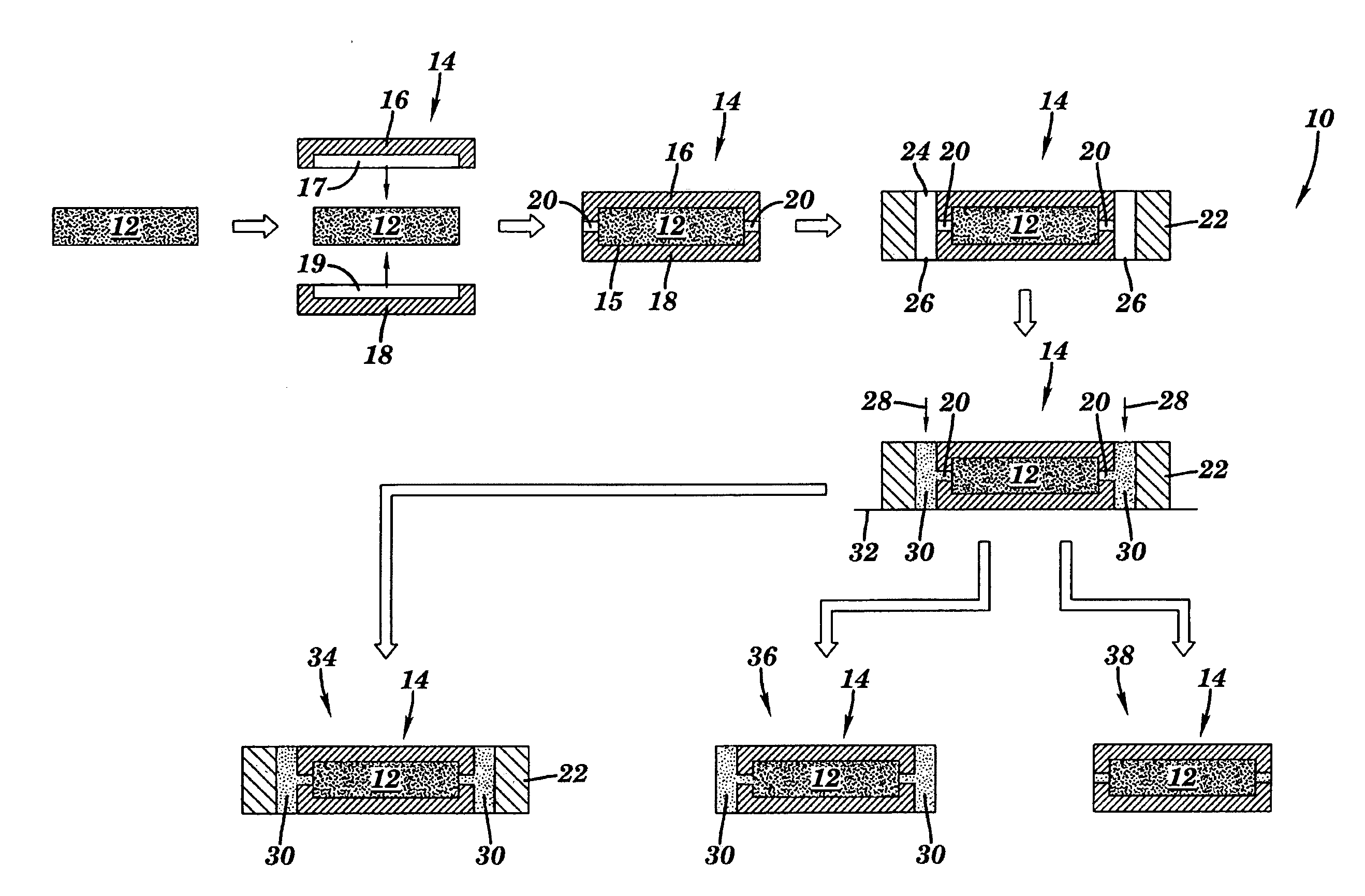
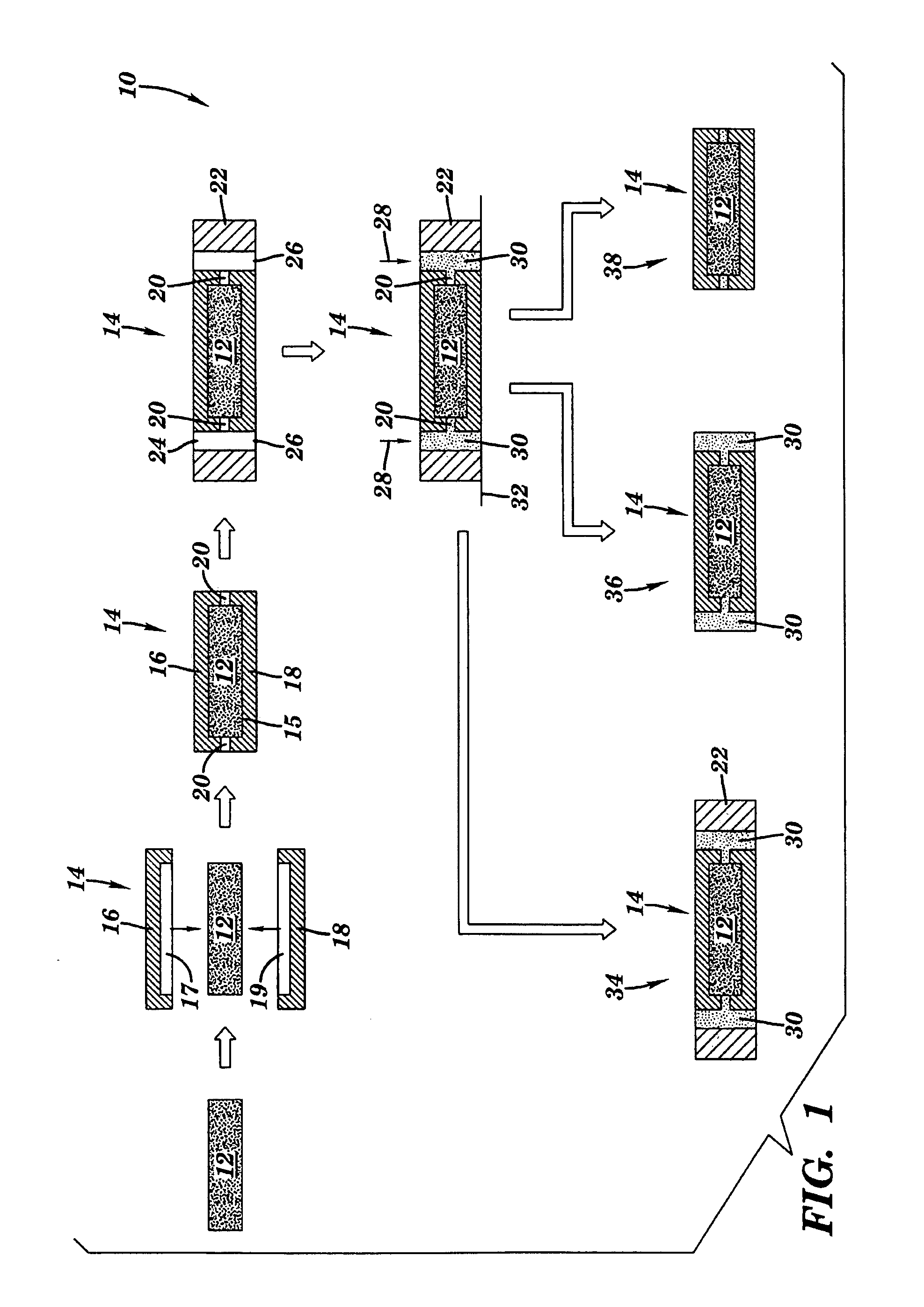
[0026]FIG. 1 is a schematic illustration of a method 10 for encasing a magnet 12 according to one aspect of the invention. Though magnet 12 shown in FIG. 1 is illustrated schematically as a rectangular block, it will be understood that magnet 12 may have any three-dimensional shape, including a cylinder, a disk, a plate, a sheet, and a parallelepiped, among other three dimensional shapes. Magnet 12 may comprise any type of conventional ferromagnetic material, both metallic and non-metallic, for example, magnet 12 may be a ferrite magnet, an aluminum-nickel-cobalt (Al-Ni-Co) magnet, or a rare-earth magnet, among other magnetic materials. In one aspect, magnet 12 may be a rare-earth magnet, for example, a samarium cobalt (SmCo) magnet, SmCo and iron magnet, a neodymium magnet, or a neodymium-iron-boron (NdFeB) magnet, among other magnetic materials.

[0027]As shown in FIG. 1, according to an aspect of the invention, magnet 12 may be inserted into a housing 14 having a cavity 15, for exa...


PUM

PropertyMeasurementUnit
hardenableaaaaaaaaaa
diameteraaaaaaaaaa
temperatureaaaaaaaaaa

Abstract

A method of encasing a magnet to isolate the magnet from the environment is provided. The method includes introducing a magnet to a housing having at least one passage capable of passing a fluid from the environment to the magnet, introducing a hardenable fluid, for example, a resin, to the passage to obstruct the passage, and solidifying the hardenable fluid in the passage to provide a solid obstruction to the passage to isolate the magnet from environmental fluids. The housing may be provided as two mating housings and the passage may be provided by the mating surfaces between the two housings. An encased magnet is also disclosed. The encased magnet may be used in any environment that may be damaging to the magnet, for example, in surgical or prosthetic applications.

Description

BACKGROUND OF THE INVENTION[0001]1. Technical Field[0002]This invention relates, generally, to methods of encasing magnets and magnets so encased. More particularly, the present invention provides improved encased magnets that can be used in environments that would otherwise damage the magnet or adversely affect the environment in which the magnet is used, such as, in prosthetic devices.[0003]2. Description of Related Art[0004]Magnets are often useful in a broad range of applications for retaining, typically, temporally, articles, or components on ferromagnetic surfaces. However, sometimes the environment or application in which a magnet is used can be damaging to the magnet or the magnet may be damaging to the environment. For example, in surgical environments, bodily fluids can be corrosive to certain magnetic materials, or magnetic material may be harmful to the patient, for instance, broken pieces of fragile magnets can be harmful to a patient. Therefore, it is often necessary t...

Claims


Application Information

Patent Timeline
Patent Type & Authority Applications(United States)
IPC IPC(8): H01F1/00B05D5/00B28B1/14
CPCB29C70/72H01F41/026B29K2105/203
Inventor SOMPLE, JESSICA KATEPELL, RANDOLPH W.HILLIARD, WAYNE
Owner MACK MOLDING
Why Eureka
Try Eureka