Plasma display panel driving method and plasma display device

a technology of plasma display panel and driving method, which is applied in the direction of instruments, computing, electric digital data processing, etc., can solve the problems of requiring higher contrast in display images for larger panels with higher definition, and achieve enhanced maximum luminance, enhanced contrast, and enhanced maximum luminance

Inactive Publication Date: 2009-08-13
PANASONIC CORP
View PDF16 Cites 7 Cited by
  • Summary
  • Abstract
  • Description
  • Claims
  • Application Information

AI Technical Summary

Benefits of technology

[0016]The present invention addresses the above problem and provides a panel driving method and a plasma display device capable of displaying a vigorous image having enhanced maximum luminance and thus enhanced contrast.
[0017]For this purpose, the panel driving method of the present invention displays an image by dividing one filed of a supplied display image into a plurality of sub-fields each having a setup period, an address period, and a sustain period. In the setup period, initializing discharge is generated in discharge cells. Each of the discharge cells includes display electrode pairs each made of a scan electrode and a sustain electrode. In the address period, addressing discharge is generated in the discharge cells. In the sustain period, sustain pulses set for each of the sub-fields are applied to the display electrode pairs to generate sustaining discharge. This method includes a step of reducing the number of sub-fields in one field period, and a step of increasing the total number of the sustain pulses in one field period, when the display image changes from a normal image to a predetermined image meeting predetermined conditions. This method further includes a step of reducing the total number of the sustain pulses in one field period, and a step of increasing the number of the sub-fields in one field period, when the display image changes from the predetermined image to the normal image. This method can provide a panel driving method and a plasma display device capable of displaying a vigorous image having enhanced maximum luminance and enhanced contrast.

Problems solved by technology

However, in recent years, larger panels with higher definition have been requiring higher contrast in the display images.

Method used


Image

  • Plasma display panel driving method and plasma display device
  • Plasma display panel driving method and plasma display device
  • Plasma display panel driving method and plasma display device

Examples


Embodiment Construction

[0051]Hereinafter, a description is provided of a plasma display device in accordance with an exemplary embodiment of the present invention, with reference to the accompanying drawings.

Exemplary Embodiment

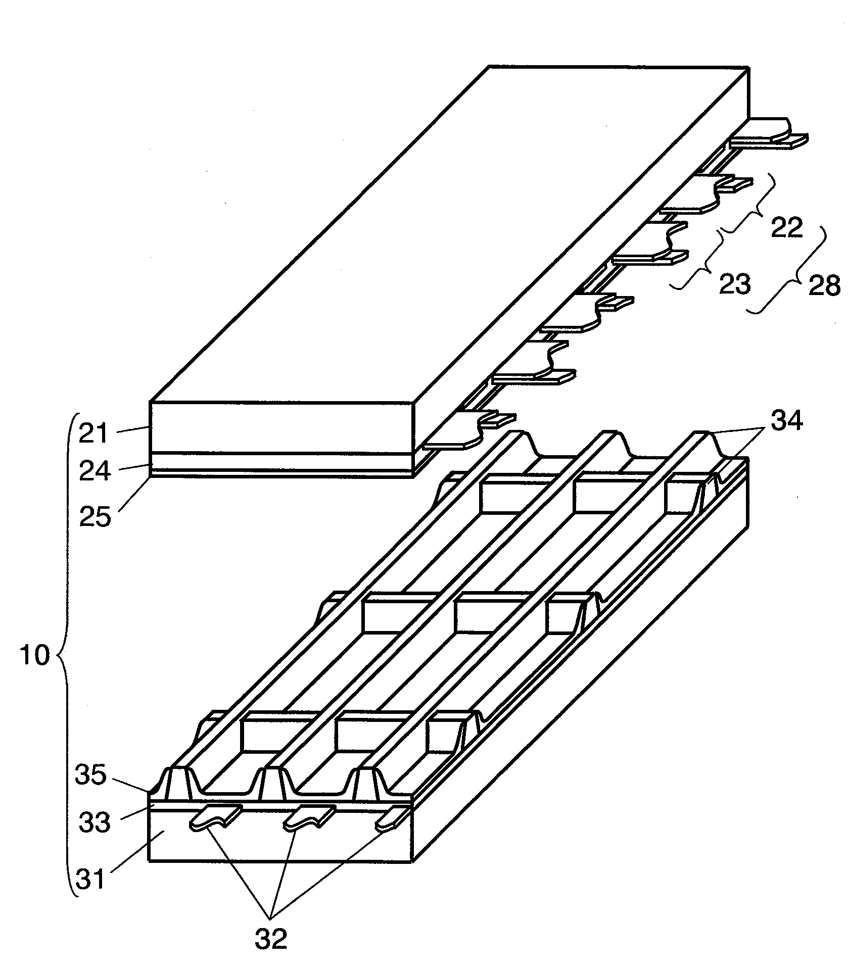
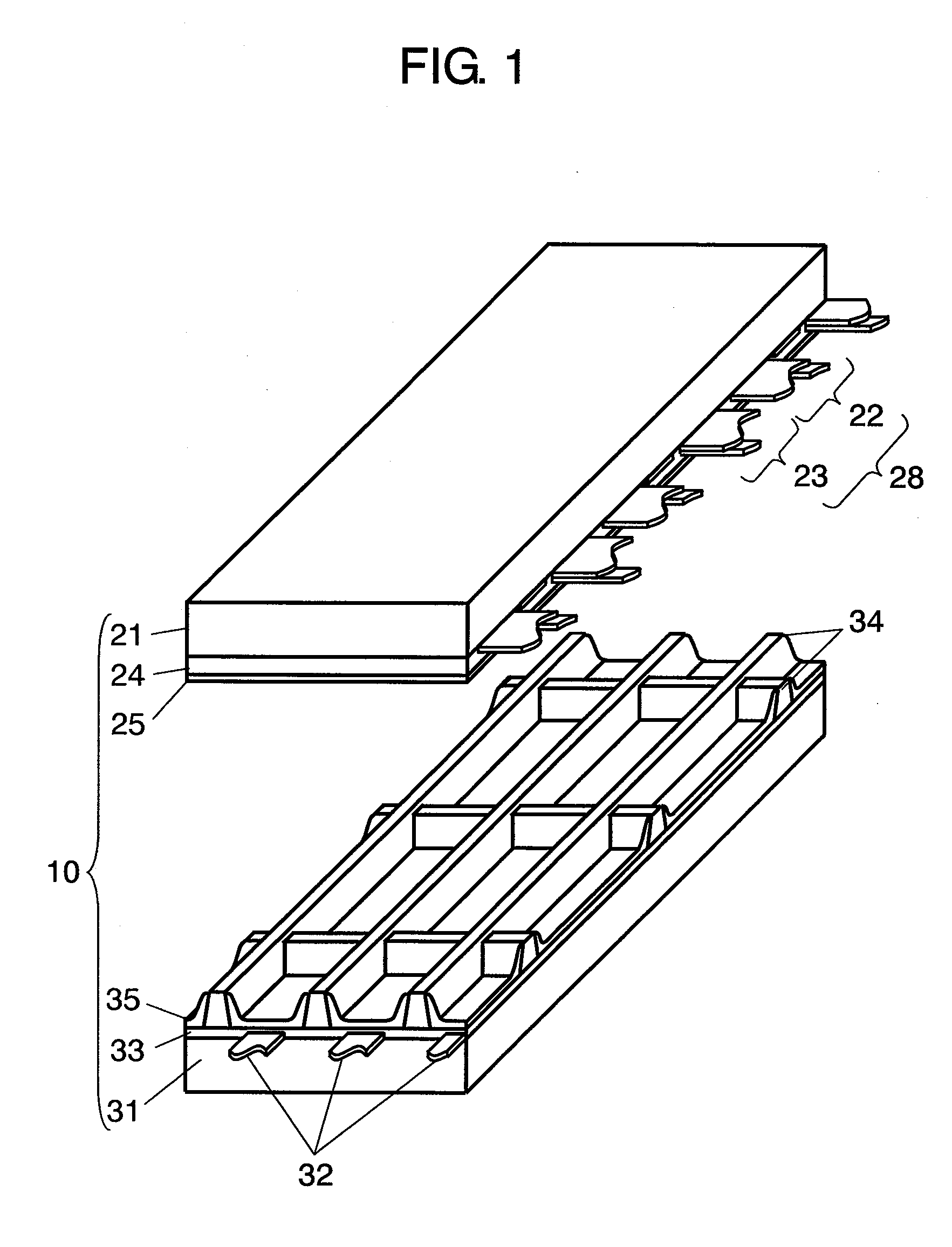
[0052]FIG. 1 is an exploded perspective view illustrating a structure of panel 10 in accordance with the exemplary embodiment of the present invention. A plurality of display electrode pairs 28, each made of scan electrode 22 and sustain electrode 23, are formed on glass front plate 21. Dielectric layer 24 is formed to cover scan electrodes 22 and sustain electrodes 23. Protective layer 25 is formed over dielectric layer 24. A plurality of data electrodes 32 are formed on rear plate 31. Dielectric layer 33 is formed to cover data electrodes 32. On the dielectric layer, barrier ribs 34 are formed in a double cross. Further, over the side faces of barrier ribs 34 and dielectric layer 33, phosphor layers 35 for emitting red (R), green (G), or blue (B) light are provided.

[0053]These fr...


PUM


Abstract

A plasma display driving method capable of displaying a vigorous image having enhanced maximum luminance and contrast. For this purpose, one field is divided into a plurality of sub-fields each including a sustain period. In the sustain period, the number of sustain pulses obtained by multiplying a proportionality factor by a brightness weight set for each of the sub-fields are applied to display electrode pairs to generate sustaining discharge in discharge cells having generated addressing discharge therein. Thus, the total number of the sustain pulses in one field period can be changed. When a predetermined image meeting predetermined conditions is displayed, the total number of the sustain pulses in one field period is made larger than those in the case where the other normal images are displayed.

Description

[0001]This application is a U.S. National Phase Application of PCT International Application PCT / JP2007 / 053293.TECHNICAL FIELD[0002]The present invention relates to a method of driving a plasma display panel for use in a wall-mounted television or a large monitor, and to a plasma display device.BACKGROUND ART[0003]An alternating-current surface-discharging panel representative of a plasma display panel (hereinafter abbreviated as “panel”) has a large number of discharge cells formed between the front plate and the rear plate faced with each other.[0004]For the front plate, a plurality of display electrode pairs, each made of a scan electrode and a sustain electrode, are formed on a front glass substrate in parallel with each other. A dielectric layer and a protective layer are formed to cover these display electrode pairs. For the rear plate, a plurality of parallel data electrodes are formed on a rear glass substrate and a dielectric layer is formed over the data electrodes to cove...

Claims


Application Information

Patent Timeline
Patent Type & Authority Applications(United States)
IPC IPC(8): G09G5/00G09G3/28G09G3/288G09G3/291G09G3/292G09G3/294G09G3/296G09G3/298
CPCG09G3/2927G09G3/294G09G2360/16G09G2310/066G09G3/2946G09G3/296
Inventor NISHIMURA, KENJIYAWATA, AKIRATANIGUCHI, HIRONARI
Owner PANASONIC CORP
Why Eureka
Try Eureka