Container assembly and latch apparatus, and related methods

a technology of latches and containers, applied in the field of container assembly and latches, can solve the problems of insufficient or secure engagement between the two adjacent parts, the latches used in many prior art containers are susceptible to improper insertion or orientation within the sidewall and/or drop door panel, and the risk of damage to the container, or to people and/or property around or in the container, so as to reduce the number of molds, easy to remove and replace/repair, and easy to inser

Active Publication Date: 2009-08-20
ORBIS CORP
View PDF121 Cites 14 Cited by
  • Summary
  • Abstract
  • Description
  • Claims
  • Application Information

AI Technical Summary

Benefits of technology

[0010]It this therefore an object of the invention to provide a improved apparatus and method for joining pieces into an assembly, in a selective manner. By using a latch apparatus, hinged elements can function in a normal hinged manner with respect to each other, but by inserting a plug or similar element in place of the latch, the hinged elements can be locked to each other. The plug or locking / assembly aspect of the invention can be utilized in a wide variety of applications, including (by way of example) joining two or more pieces to each other even when there is not any hinged relationship between those pieces.
[0011]Another object of the invention is to provide improved latch apparatus and methods. Latches embodying the invention are useful in conjunction with the foregoing hinged elements and methods, or in other applications. In the preferred embodiments of the latch, the latch can be readily inserted and manipulated (to engage and disengage two things with each other); and readily removed and replaced / repaired. For embodiments such as described above; the latch preferably can be selectively replaced with a plug member of similar size and shape, to provide a relatively more permanent connection between the two things. Thus, and as described above and herein, one of the many applications in which the invention finds utility in providing the capability to readily convert collapsible containers or other bulk containers from open (drop door or access panel versions) to solid sidewalls, or vice versa.
[0012]In one embodiment, the invention provides for a molded bulk container consisting of a base and four sidewalls, where either a sidewall(s) with an access (drop) door or a solid sidewall can be assembled from the same molded components (an open side sidewall and a drop door). The desired configuration can be selected by inserting either door latches (for the access door version) or a latch plug (for the solid sidewall version), and preferably the assembly can be readily converted from either configuration to the other repeatedly, as the user desires or as circumstances demand. The open side sidewall and drop door thus can essentially form a solid sidewall by fixing the drop door in place by means of the plug.
[0013]An additional object of the invention is to reduce the number of molds or mold insert and / or eliminate the need to change molds or use mold inserts in the production or manufacturing process, when changing from solid to open side sidewalls (or vice versa). Among its many benefits, certain aspects of the invention permit the same molds (with no change or insert) and the pieces resulting from those mold to be used to make both (a) “solid” sidewalls and (b) access panel / drop door sidewalls.
[0014]An additional object of the invention is to provide a convertible container of the aforementioned character, in which the “solid wall” condition can be achieved without the presence of any hinges. Among other things, for customers and / or applications where no need for hinging is anticipated, the “solid” wall assembly can be provided without any hinges (thereby saving on costs, weight, etc. as compared to including a hinge in those “solid wall” embodiments). For such embodiments, the invention preferably includes interfering structures acting between the drop door and the sidewall, such structures engaging each other when inward and or outward forces are applied on the “solid wall” to increase the strength of the assembly. Among other things, these interfering structures can be similar to a tongue-and-groove construction, and can reduce the likelihood that such inward or outward forces might cause a gap between the bottom of the drop door and the confronting top of the sidewall (at the location where the hinge(s) normally would be) or might otherwise cause the sidewall / container to fail under such loading conditions.
[0015]By instead using certain embodiments of the invention, manufacturers need only fabricate and inventory (and sell, etc.) the components of the “drop door” version, because those components can be “pinned” to each other using the invention, to form a “solid” (non-drop-door) sidewall. The apparatus and methods of the invention also can simplify and improve the quality and efficiency of manufacture, installation, and removal of latches, such as those associated with separate, hinged and / or adjacent elements.

Problems solved by technology

In addition, the latches used in many prior art containers are susceptible to improper insertion or orientation within the sidewall and / or drop door panel.
If a latch is inserted “backwards” or otherwise improperly, it may not sufficiently or securely engage the two adjacent parts, risking damage to the container, or to people and / or property around or in the container.
This results in potential confusion, lost assembly time, and mistakes in assembly (drop door latches may be inserted into sidewall latch positions) both during manufacture and maintenance.
It also requires that manufacturers and users (for manufacture, maintenance, and replacement purposes) carry a relatively complex and extensive inventory of latches and related parts.
Prior art latches typically do not provide an optimum balance between (a) ruggedness and security once assembled within the container, and (b) ease of assembly / replacement / maintenance as the need may arise.
Among other approaches, prior art designs include interfering tabs behind which the latches must be forced during insertion.
In practice, removal of the latch from behind the tab can be significantly difficult or can even result in destroying the tab or sidewall / drop door itself.
If the tab is broken or weakened by such removal (or otherwise is broken during use of the container), the latch typically can no longer be retained in the sidewall or drop door by the tab.
Such “permanent” affixation of the replacement latch not only takes more time than is desirable, but makes any subsequent replacement or maintenance on the latch even more difficult and time-consuming.
Further on that point, and specifically regarding collapsible containers, typical prior art latches are not reversible or otherwise usable for both sidewall latching and drop door latching.

Method used


Image

  • Container assembly and latch apparatus, and related methods
  • Container assembly and latch apparatus, and related methods
  • Container assembly and latch apparatus, and related methods

Examples


Embodiment Construction

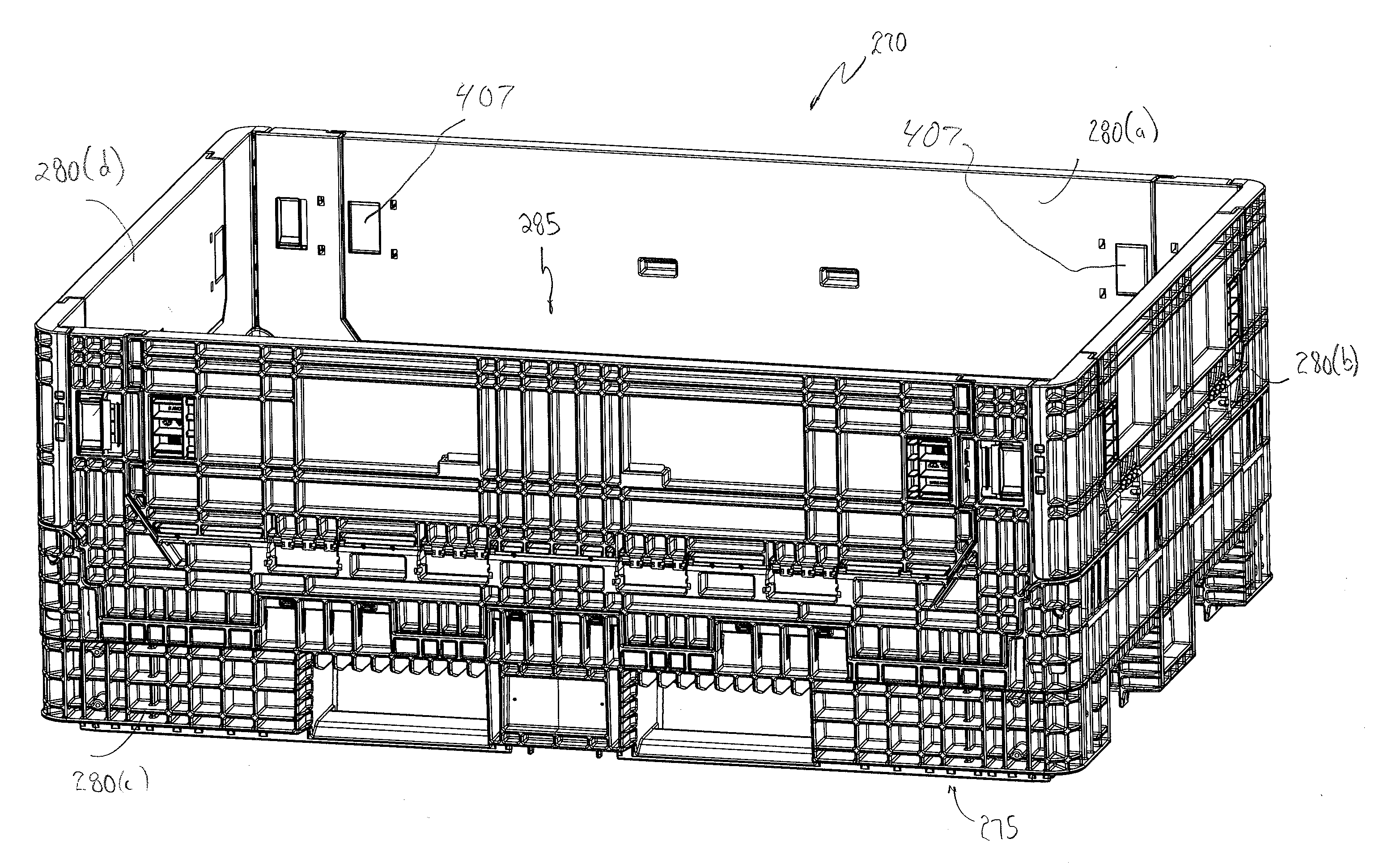
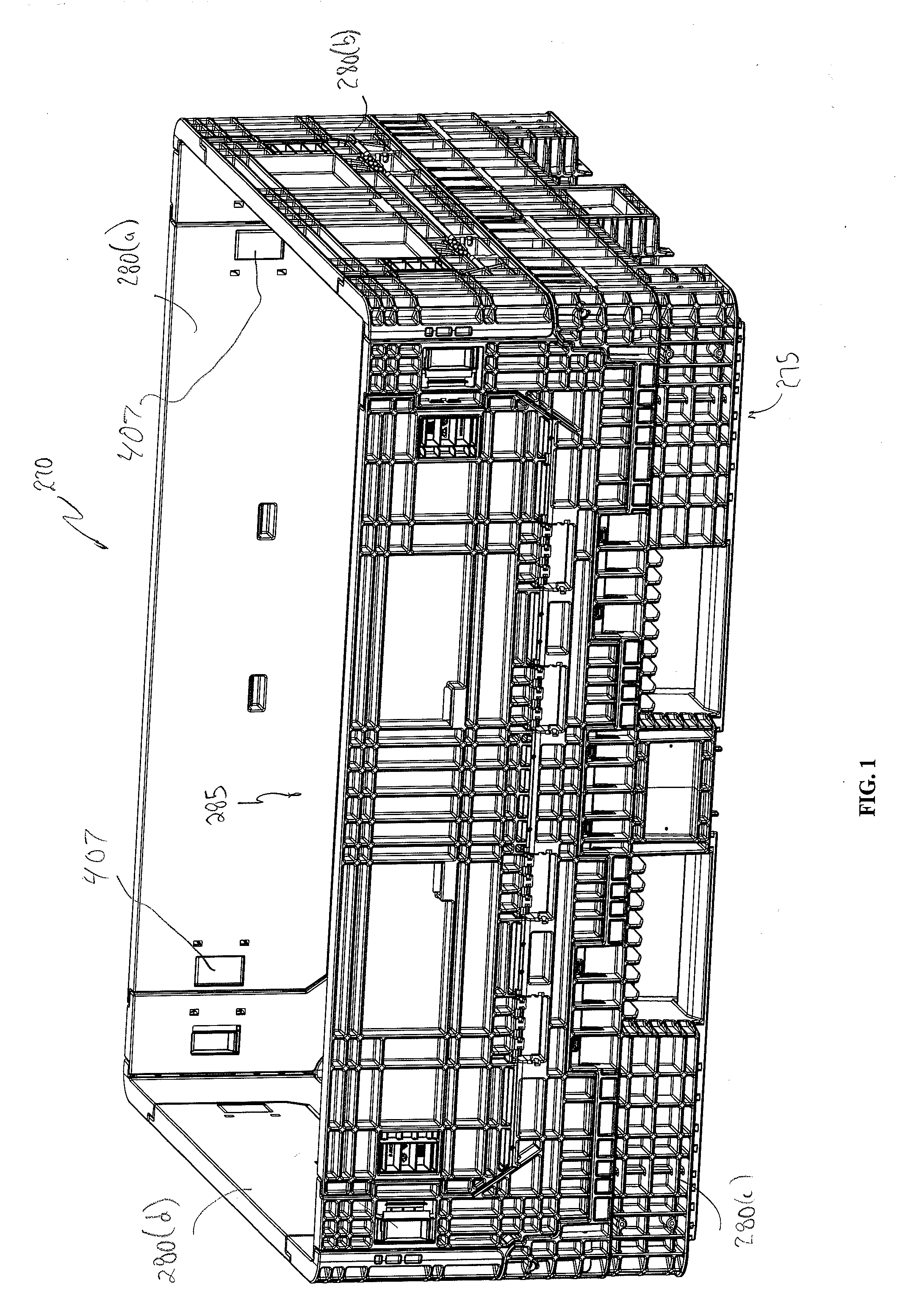
[0038]Persons of ordinary skill in the art will understand that the components discussed herein can be fabricated from any of a wide variety of materials and processes. Preferably, the components are lightweight but suitably strong to withstand the loads and forces they may encounter during use. Among others, high / low pressure plastic injection molding, structural foam molding, or blow-molding can be readily utilized to form lightweight components or structures embodying the invention, for storage, transport, and handling of a wide variety of solid and liquid materials and things. Other fabrication methods include, by way of example, compression molding, rotational molding, gas / water assist molding, extrusion, or pultrusion.

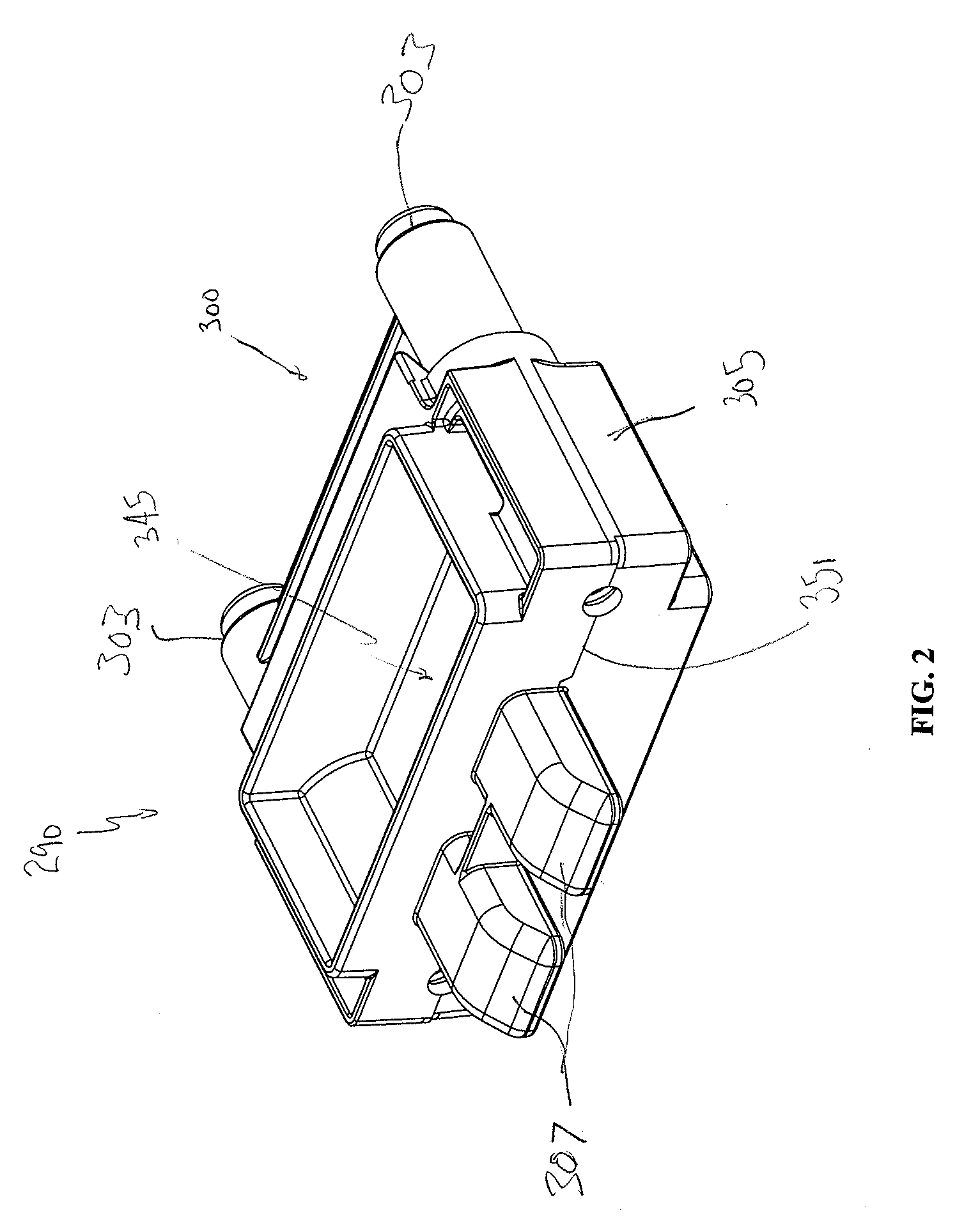
[0039]For certain of the components described herein, materials such as nylon may be preferable (for certain latch and plug components), while alloy steel may be useful for other latch embodiments. Persons of ordinary skill in the art will understand that other m...


PUM

PropertyMeasurementUnit
compressive forcesaaaaaaaaaa
forceaaaaaaaaaa
forcesaaaaaaaaaa

Abstract

Apparatus and methods for engaging and disengaging various members (280) to each other are described herein. The preferred apparatus and methods reduce the number of components and/or sub-assemblies in hinged apparatus (270) and methods and other applications, and simplify and improve the quality and efficiency of installation and removal of latches (290) associated with the hinged elements or members (280). The latching/locking system and methods of the invention also enable selective relatively permanent engagement of the hinged elements or members (280) to each other, and can permit selective transition between the foregoing hinged and locked relationships. Improved latches (290) are disclosed, with interchangeability, keying to assist assembly, and other features. Methods of fabrication and assembly are disclosed.

Description

BACKGROUND OF THE INVENTION[0001]The invention relates generally to containers and components thereof, and specifically to apparatus and methods for engaging and disengaging various members of a container or similar apparatus to each other. Although the invention is primarily illustrated in connection with various components of a collapsible container, it has a wide range of potential applications and uses other than for containers.[0002]Prior art bulk containers (especially those that are injection molded or blow-molded or otherwise formed from plastic) sometimes include an option of having one or more sidewalls that either (1) are solid, or (2) include multiple parts moveable with respect to each other. An example of the latter is a sidewall with a fold down access door (or “drop door”). The access door typically is hinged in an opening in the sidewall and can be secured in alignment with the sidewall (by latches or some other interlock).[0003]Prior art bulk containers are sometim...

Claims


Application Information

Patent Timeline
Patent Type & Authority Applications(United States)
IPC IPC(8): E05D11/10B65D6/18B29C45/14
CPCB65D11/18B65D19/18B65D2519/00034B65D2519/00069B65D2519/00174B65D2519/00243Y10T16/5402B65D2519/00417B65D2519/00422B65D2519/00611B65D2519/00661E05C1/10B65D2519/00333
Inventor NOLAN, ROGERTURNER, TODD
Owner ORBIS CORP
Why Eureka
Try Eureka