System and Method for Determining Target Range and Coordinating Team Fire

a range finding and target range technology, applied in the field of system and method for determining target range and coordinating team fire, can solve the problems of dangerous use of range finding devices emitted by signal scattering, inconvenient use, and difficulty in accurately predicting the impact point of projectiles

Inactive Publication Date: 2009-08-20
SMITH THOMAS D III
View PDF31 Cites 74 Cited by
  • Summary
  • Abstract
  • Description
  • Claims
  • Application Information

AI Technical Summary

Problems solved by technology

However, due to certain forces on projectiles while in flight after the gun or weapon system has shot or launched the projectile, aiming and predicting accurately the point of impact of a projectile is more difficult than just determining a straight “line of sight” from the muzzle of the gun to a target.
Beginning shooters do not recognize the problem, but advanced and precision shooters, however, agree that such a simplification is unreliable for humane harvest of sentient animals or critical situations, such as hostage rescue team snipers, and for long range missions, such as military snipers.
In certain scenarios, however, use of a range finding device which emits a “scatter” of signal can be dangerous and contraindicated.
So, use of a laser range finder in a covert application on a battlefield may result in revealing the location of personnel.
But, these techniques remain math-intensive, are extremely distracting to the essential psychopsysiological performance state required for a successful shot, and are not conducive to practice by shooters of limited math skills or education.
In a different, but related problem, training of users of scope-equipped guns remains difficult because a coach is unable to see in real-time what the shooter is seeing.
Coordination and command is usually performed by a centralized authority, but again, the central authority is unable to actually see what the team members can see via their scopes.

Method used


Image

  • System and Method for Determining Target Range and Coordinating Team Fire
  • System and Method for Determining Target Range and Coordinating Team Fire
  • System and Method for Determining Target Range and Coordinating Team Fire

Examples


Embodiment Construction

[0029]For the reader's conveniences, issued U.S. Pat. Nos. 7,237,355; 7,222,452; 7,194,838; 7,069,684; 6,591,537; D456,057; and 6,357,158 provide a great deal of background information regarding riflescopes and use of my other riflescope inventions. The present invention is preferably realized in conjunction with my previous riflescope inventions, but may be realized separately, as well.

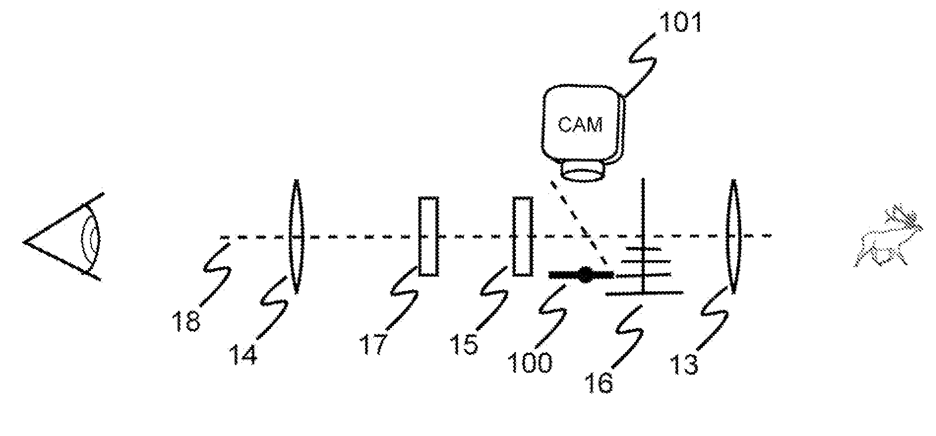
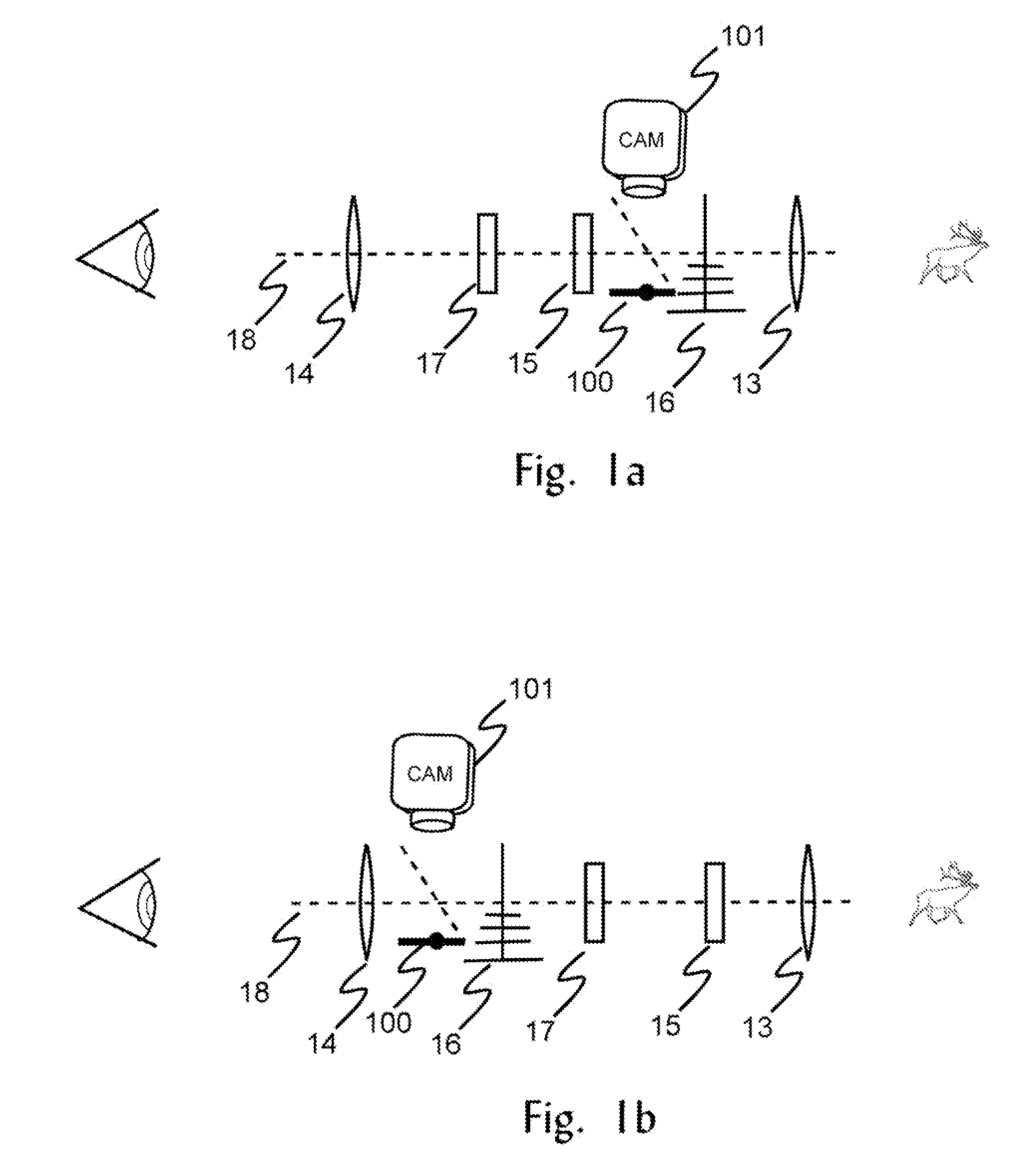
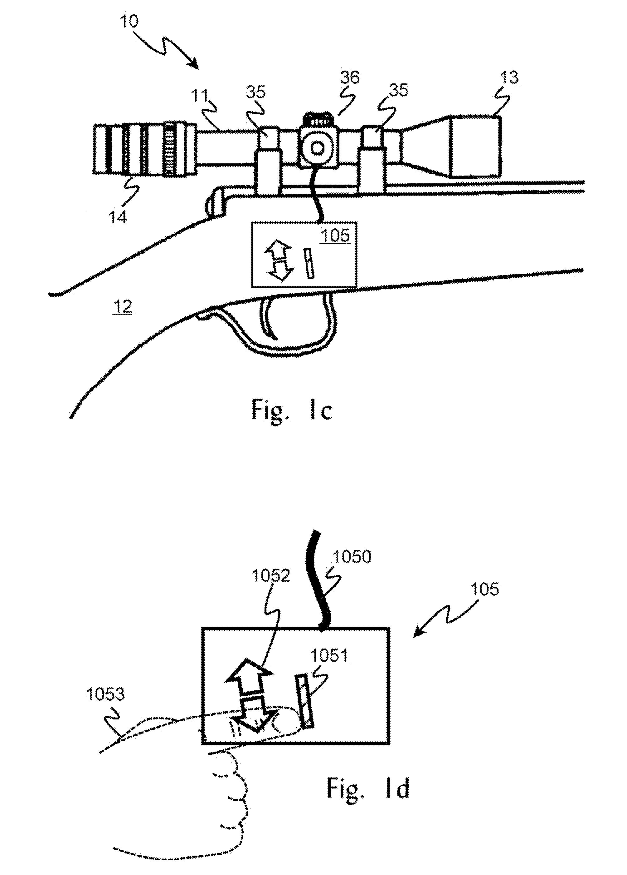
[0030]Turning to FIGS. 1a-1c, a telescopic sight 10, embodying this invention is shown attached by a suitable mount 35 to a gun 12. The sight 10 is formed by a tubular housing 11 containing a forwardly positioned objective lens element 13, a rearwardly positioned ocular or eyepiece lens element 14, an intervening erector lens element 15, and a reticle 16 disposed between the objective lens element 13 and the erector lens element 15. In the case of vari-focal or zoom scopes, a positionally adjustable magnifying lens 17 is associated with the erector lens element 15. The exterior of the housing 11 may ...


PUM


Abstract

A system and method for use of an enhanced aiming system which includes a marker displayed at a first position in an aiming scope, a user input of a start position and an ending position to measure a desired impact zone, a calculator for determining a range to the target based on the known dimension of the impact zone and the magnification value of the aiming scope, and a display in the aiming scope for showing an aiming point dot or bar to compensate for projectile drop at the calculated range, and optionally for windage and optionally for moving target hold-over.

Description

CROSS-REFERENCE TO RELATED APPLICATIONS[0001]This application claims benefit of the filing date of provisional patent application 61 / 029,203, docket number TDSEM2008P, filed on Feb. 15, 2008, by Thomas D. Smith, III.FEDERALLY SPONSORED RESEARCH AND DEVELOPMENT STATEMENT[0002]This invention was not developed in conjunction with any Federally sponsored contract.MICROFICHE APPENDIX[0003]Not applicable.INCORPORATION BY REFERENCE[0004]Issued U.S. Pat. Nos. 7,237,355; 7,222,452; 7,194,838; 7,069,684; 6,591,537; D456,057; and 6,357,158; and U.S. provisional patent application 61 / 029,203, docket number TDSEM2008P, filed on Feb. 15, 2008, are hereby incorporated by reference in their entireties.BACKGROUND OF THE INVENTION[0005]1. Technical Field of the Invention[0006]This application relates to displays within scopes used for aiming rifles, pistols, and other projectile delivery systems. It especially relates to determining range-to-target values, providing range and windage-corrected aiming...

Claims


Application Information

Patent Timeline
Patent Type & Authority Applications(United States)
IPC IPC(8): F41G1/38
CPCF41G1/38F41G3/08F41G3/06
Inventor SMITH, III, THOMAS D.
Owner SMITH THOMAS D III
Why Eureka
Try Eureka