Eureka AIR delivers breakthrough ideas for toughest innovation challenges, trusted by R&D personnel around the world.

Modularized Self-sustaining Building System

Inactive Publication Date: 2009-08-20
FENNELL JAMES R
View PDF12 Cites 16 Cited by
  • Summary
  • Abstract
  • Description
  • Claims
  • Application Information

AI Technical Summary

Benefits of technology

[0008]Many agencies, for example rural fire service, must set up stations in remote locations where there is no easy access to utility services. The present invention is electrically self-sustaining, designed with photovoltaic collection arrays and wind generator to collect and distribute power, stored in battery ce

Problems solved by technology

Many agencies, for example rural fire service, must set up stations in remote locations where there is no easy access to utility services.

Method used


Image

  • Modularized Self-sustaining Building System
  • Modularized Self-sustaining Building System
  • Modularized Self-sustaining Building System

Examples


Embodiment Construction

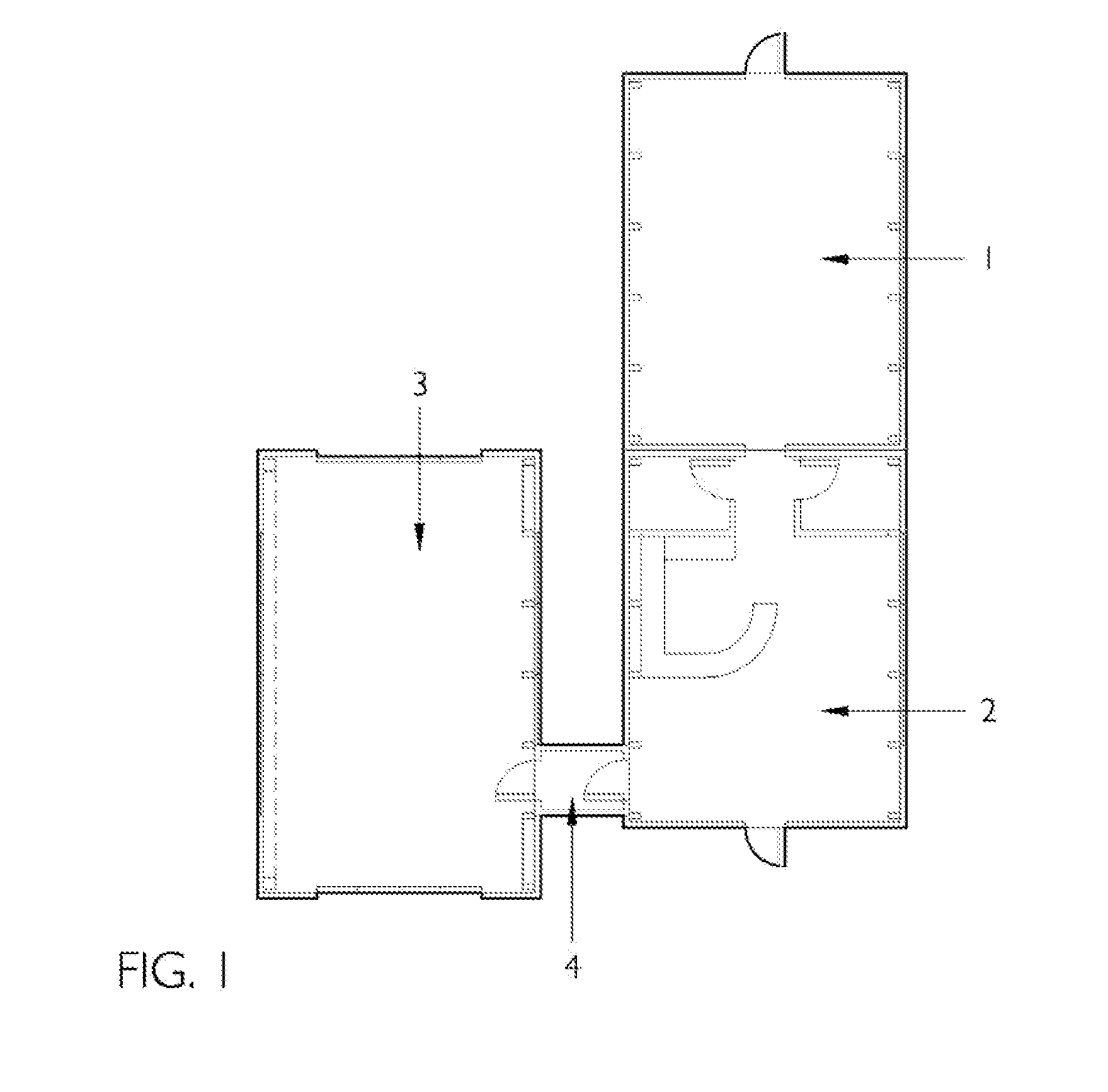
[0037]The complete physical integration of the modules for the preferred embodiment is illustrated in FIG. 1. The floor plan shows the sleep / work module 1, the water-use module 2, the service bay module 3, and the connector module 4. Each of the functional modules, sleep / work, water-use, and service bay, are designed so that additional modules can be easily assembled and integrated for larger facilities than are illustrated in this embodiment. Although FIG. 1 illustrates only one sleep / work module, one water-use module, and one service bay, each module is self-sustaining and expansion is easily accommodated by providing interior doors. The connector module 4 is primarily to transition between a sleep / work or water-use module and the service bay module.

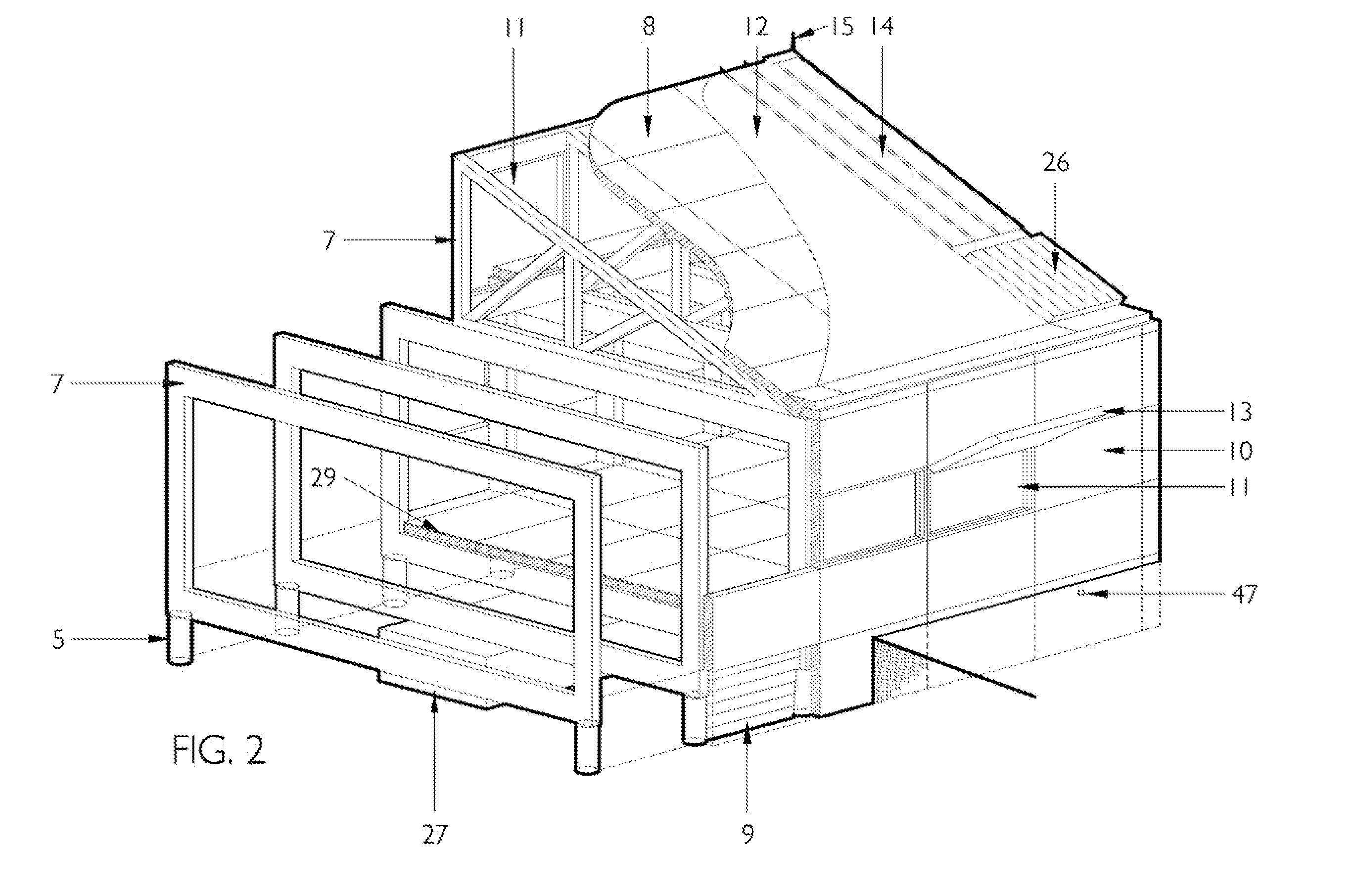
[0038]FIGS. 2, 6, and 10 illustrate how each module utilizes the same helical pier foundation 5 system. The piers are augured into the earth leaving the top of the pier flush with the finished grade, which is approximately six inches b...


PUM


Abstract

A self-sustaining modularized building system comprised of prefabricated components. The self-sustaining utilities are fully integrated into the modules, allowing service and protection agencies to operate in remote areas in an eco-friendly manner.

Description

BACKGROUND OF INVENTION[0001]The present invention relates to self-sustaining modularized building systems designed primarily but not exclusively for services and protections agencies. The modularized building system components are of three possible module types that are prefabricated to include self-sustaining utilities. The three module types include service bay modules, sleep / work modules, and water-use modules. The modules are all designed with active and passive solar features. The water-use modules are designed to use local or transported water, then recycle and reuse until considered wastewater.[0002]Service and protection agencies, including emergency response, fire service, airport services, military, and disaster relief often operate in areas away from utility access or make an institutional choice to operate in an eco-friendly manner. The present invention addresses the need for the application of utilities in an eco-friendly manner based on modular design principles.[000...

Claims


Application Information

Patent Timeline
IPC IPC(8): E04H14/00E04B1/348E04H1/02F24D18/00
CPCE03B1/04Y02B30/52E03B2001/045E03C1/00E04B1/24E04B1/26E04B2001/249F24D11/003F24D12/02F24D2200/02F24D2200/11F24D2200/12F24D2200/14F24D2200/15F24D2200/20F24D2200/26F24H2240/02F24H2240/09Y02B10/20Y02B10/30Y02B10/40Y02B10/70Y02B30/14E03B1/042Y02A30/60Y02B30/00F24D2105/00F24D18/00F24D2101/20F24D2101/40
Inventor FENNELL, JAMES R.
Owner FENNELL JAMES R
Why Eureka
Eureka Blog
Learn More