Gas burner head
a burner head and burner technology, applied in the field of burner head of gas stoves, can solve the problems of inconvenient use for common users, certain danger in changing the height of ignitors, and the burner head structure designed in the prior art can only be applied to low levels, so as to achieve the effect of simple and convenien
- Summary
- Abstract
- Description
- Claims
- Application Information
AI Technical Summary
Benefits of technology
Problems solved by technology
Method used
Image
Examples
first embodiment
The First Embodiment
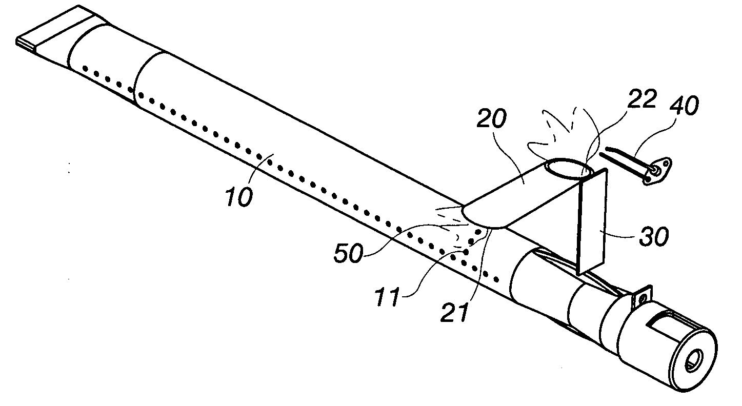
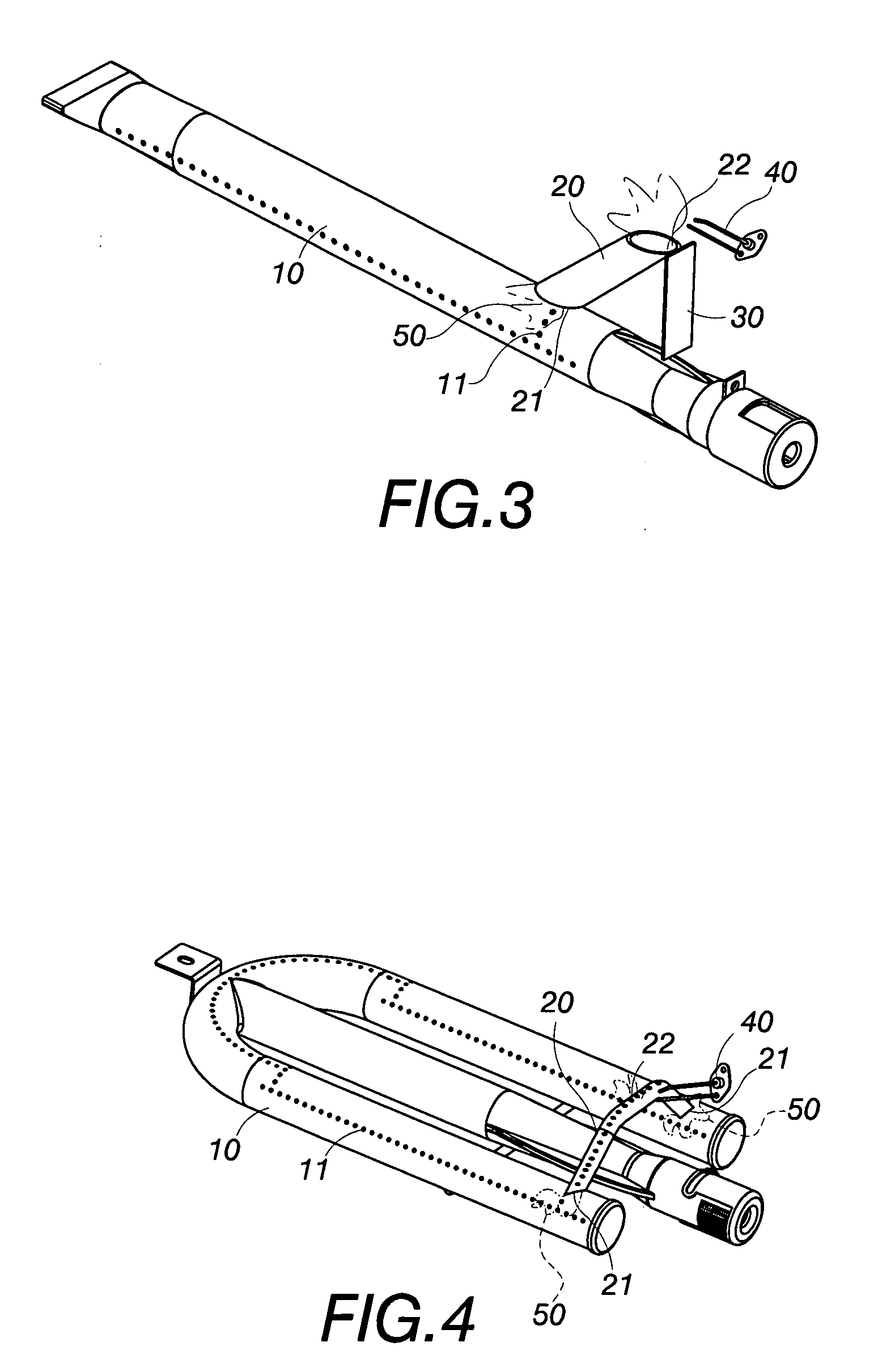
[0023]As shown in FIG. 3, a gas burner head of the present invention includes a main body of the burner head 10, a kindling pipe 20, a fixing rack 30 and an ignitor 40; in the drawing depicted, the burner head 10 and the kindling pipe 20 are linear styles.
[0024]Wherein the ignitor 40 is a high level ignitor; the fixing rack 30 is a sheet like thin plate, its lower end is fixed on the burner head 10, its height end is matched with that of the ignitor 40; an gas intake port 21 of the kindling pipe 20 is aimed at fire holes 11 of the burner head 10 and is fixed, the embodiment uses the mode of soldering for fixing; an gas out take port 22 of the kindling pipe 20 is fixed by soldering on the top end of the fixing rack 30 on the upper surface of the burner head 10.
[0025]Generally, the linear style burner head 10 is mounted at a position in corresponding to that of a low level ignitor, the ignitor can ignite it normally after kindling; when it is desired to change the ...
second embodiment
The Second Embodiment
[0027]As shown in FIG. 4, the main body of the burner head 10 is in the shape of “U”, the kindling pipe 20 is in the shape of reversed “U” or “V”, and the ignitor 40 is a high level ignitor.
[0028]Wherein, the reversed “U” or “V” shaped kindling pipe 20 is provided on its two lateral sides each with an gas intake port 21 in alignment with the fire holes 11 of the “U” shaped burner head 10, and the two gas intake ports 21 are fixed respectively on the burner head 10 by soldering; the kindling pipe 20 is provided on its body with a plurality of gas out take ports 22 lined in a straight line, and the height of the gas out take port 22 is matched with that of the high level ignitor 40.
[0029]Generally, the “U” shaped burner head 10 is mounted at a position in corresponding to that of a low level ignitor, so that the ignitor 40 can ignite normally after kindling; when it is desired to change the position of the burner head 10 in corresponding to that of the high level ...
third embodiment
The Third Embodiment
[0030]As shown in FIGS. 5 and 6, the burner head 10 is a linear forged burner head, the kindling pipe 20 is in a linear shape too, the high level ignitor 40 is a high level ignitor. Wherein forged burner head 10 is provided on its two lateral sides with fire holes 11, the linear kindling pipe 20 is fixed on the left side the front end of the burner head 10, and the height of the linear kindling pipe 20 is nearly equal to that of the ignitor 40, the gas intake port 21 is aimed at fire holes 11 on one side of the burner head 10, and the gas out take port 22 is aligned with the ignitor 40.
[0031]Generally, the linear style burner head 10 is mounted at a position in corresponding to that of a low level ignitor, so that the low level ignitor can ignite normally after kindling; when it is desired to change the position of the burner head 10 in corresponding to that of the high level ignitor 40, now a combustion gas valve (not shown) is opened to allow combustion gas to ...
PUM
 Abstract
Description
Claims
Application Information
 - R&D
- Intellectual Property
- Life Sciences
- Materials
- Tech Scout
- Unparalleled Data Quality
- Higher Quality Content
- 60% Fewer Hallucinations
Browse by: Latest US Patents, China's latest patents, Technical Efficacy Thesaurus, Application Domain, Technology Topic, Popular Technical Reports.
© 2025 PatSnap. All rights reserved.Legal|Privacy policy|Modern Slavery Act Transparency Statement|Sitemap|About US| Contact US: help@patsnap.com


