Configuring the operation of an alternating pressure ventilation mode

a technology of alternating pressure and ventilation mode, which is applied in the direction of valves, respirators, operating means/releasing devices, etc., can solve the problems of not being able to and the clinician may not agree on an appropriate, fixed time value for t/sub>low /sub>135/b>, and may no longer achieve the desired physiologic respons

Inactive Publication Date: 2009-08-20
TYCO HEALTHCARE GRP LP
View PDF104 Cites 156 Cited by
  • Summary
  • Abstract
  • Description
  • Claims
  • Application Information

AI Technical Summary

Benefits of technology

[0016]Other embodiments of the present invention provide a ventilation system, which includes a gas flow path, a pressure controller, one or more flow sensors, a user interface, a processor and a computer-readable medium. The gas flow path is to deliver breathing gas from a gas source to a patient. The pressure controller is located along the gas flow path and configured to cycle the ventilation system among a plurality of pressure settings. The one or more flow sensors are located along the gas flow path and are configured to monitor a flow of gas between the patient and the ventilation system. The user interface is configured to display information to an end user of the ventilation system regarding airway pressure of the patient and the flow of gas and to receive information from the end user indicative of one or more values of parameters associated with an alternating pressure ventilation mode of the ventilation system or from which the one or more values can be derived. The computer-readable medium has stored thereon instructions executable by the proc

Problems solved by technology

Notably, however, in the context of APRV, there is currently no consensus regarding an appropriate value of TLOW 135.
At least one drawback of this current approach of configuring an APRV mode is that the timing at which the target percentage of PEFR

Method used


Image

  • Configuring the operation of an alternating pressure ventilation mode
  • Configuring the operation of an alternating pressure ventilation mode
  • Configuring the operation of an alternating pressure ventilation mode

Examples


Embodiment Construction

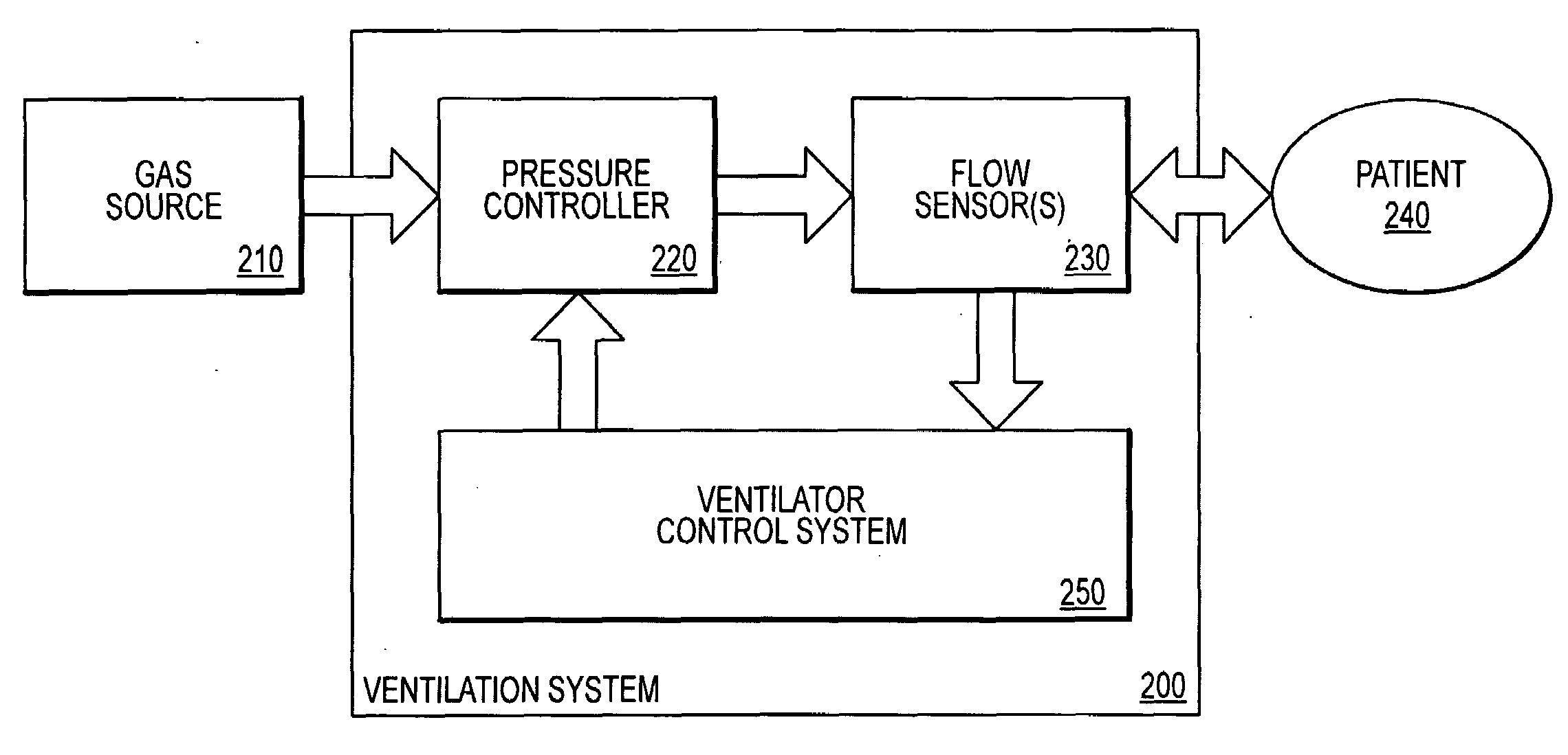
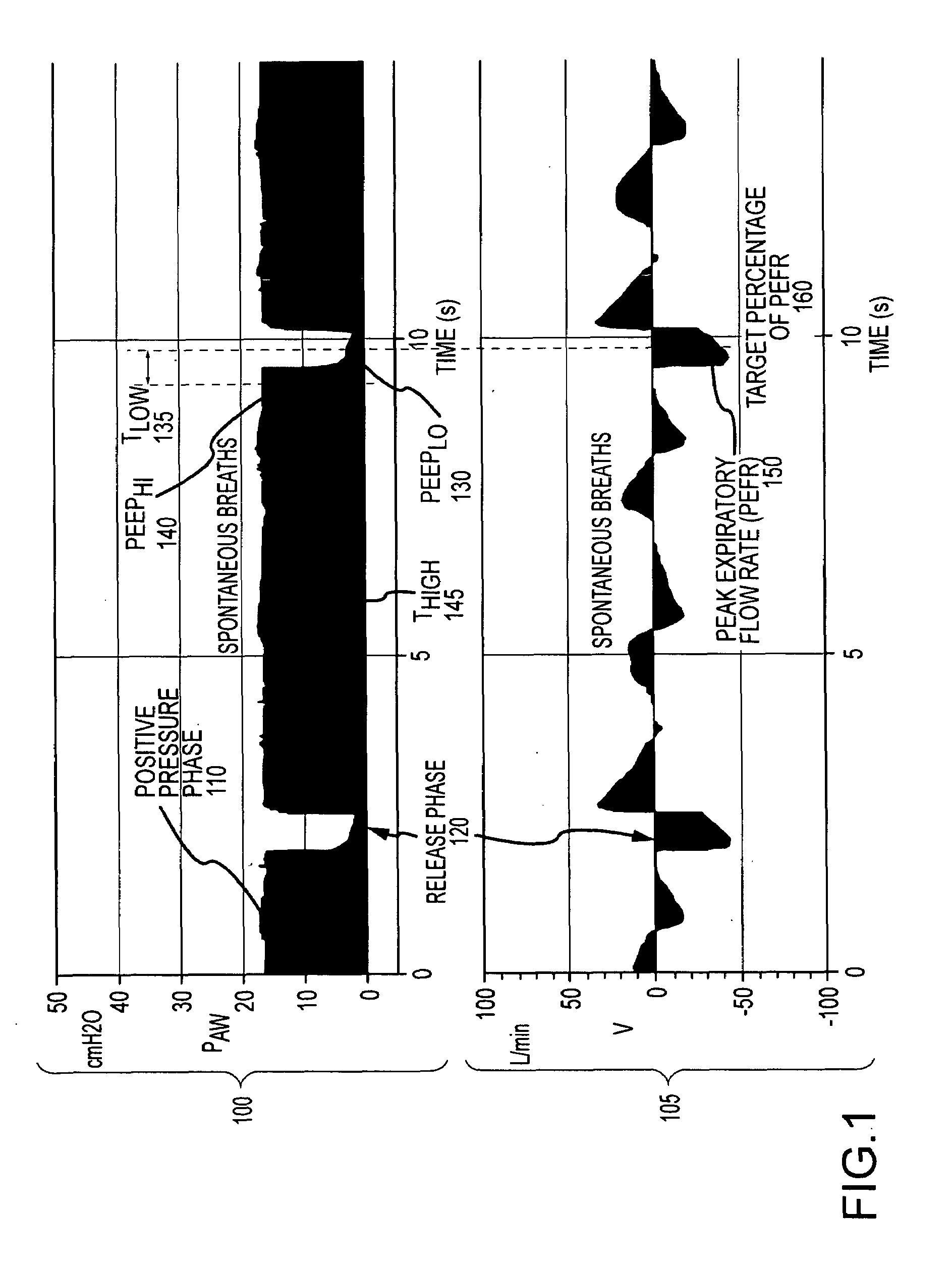
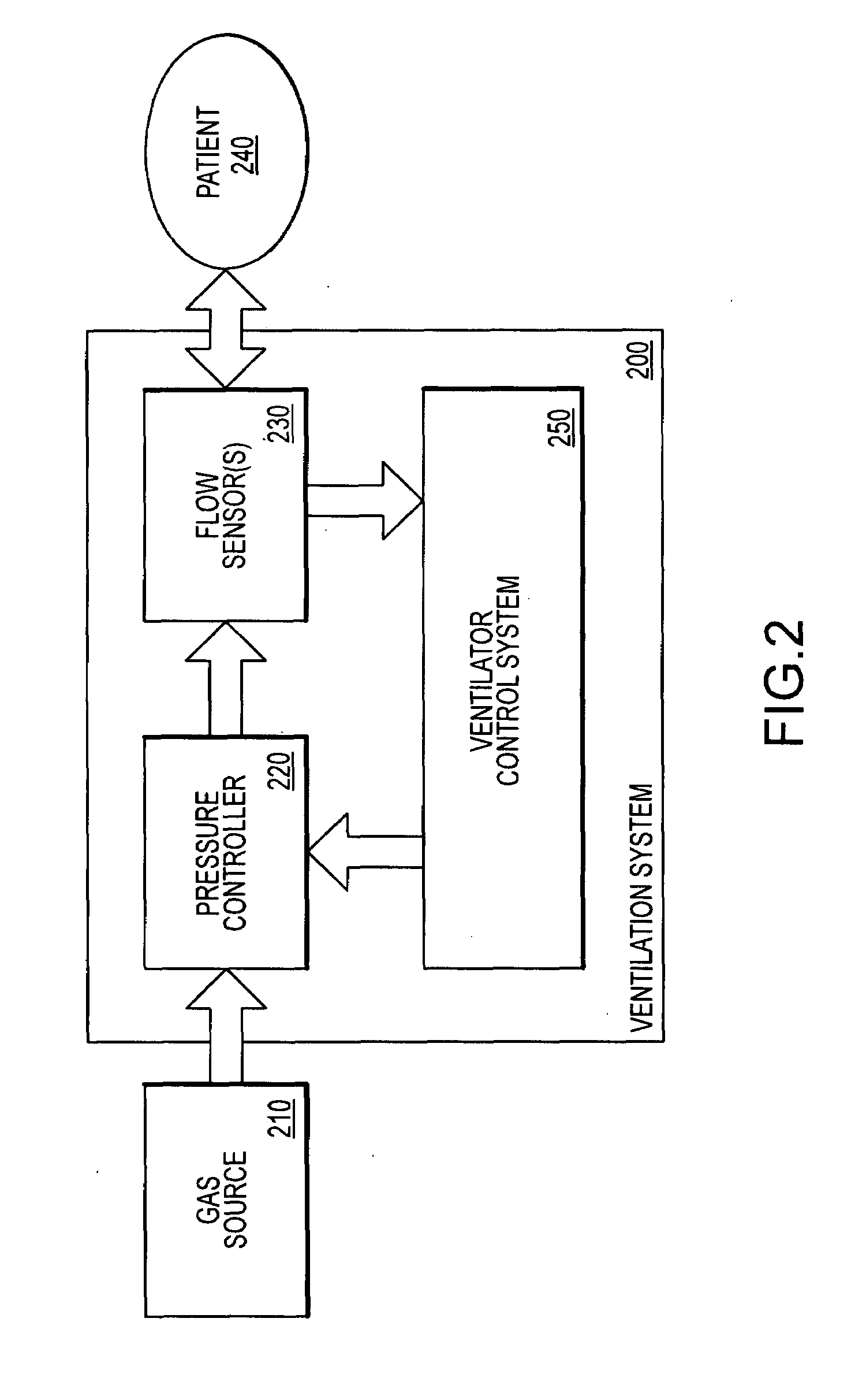
[0028]Systems and methods are described for configuring the operation of an alternating pressure ventilation mode. Increased clinical focus on recruitment of functional lung in various disease states has created a high degree of interest in using inverse inspiratory to expiratory time ratio (I:E ratio) alternating pressure ventilation modes. Such ventilation strategies are focused on maintaining the lungs in a distended state sufficient to keep all recruitable alveoli open, but to augment ventilation by periodically releasing pressure to allow better clearance of alveolar carbon dioxide. Various embodiments of the present invention provide an improved ventilation system user interface that both simplifies initiation of an alternating pressure ventilation mode and maintains the optimality of TLOW. In one embodiment of the present invention, rather than requiring the clinician to estimate TLOW based on the clinician's desired target percentage of PEFR, the clinician may directly input...


PUM


Abstract

Systems and methods for configuring the operation of an alternating pressure ventilation mode are provided. According to one embodiment a configuration method includes monitoring gas flow between a patient and a ventilation system. Based on the monitoring, a peak expiratory flow rate (PEFR) is determined Information indicative of values of parameters of the ventilation mode are received, including a higher pressure setting, a lower pressure setting and a duration of the higher pressure setting. User input is also received indicative of a target percentage of PEFR at which the ventilation system should cycle from the lower pressure setting to the higher pressure setting. Based on the target percentage, a duration of the lower pressure setting is programmatically determined. Finally, the ventilation system is configured to automatically cycle between the higher and lower pressure setting at a predetermined flow based on the parameters and the duration of the lower pressure setting.

Description

RELATED APPLICATION[0001]This application claims priority from U.S. patent application Ser. No. 61 / 029,894 which was filed on Feb. 19, 2008, and is incorporated herein by reference in its entirety.BACKGROUND OF THE INVENTION[0002]Embodiments of the present invention generally relate to mechanical ventilation, and more particularly to systems and methods for configuring the operation of an alternating pressure ventilation mode in support of various ventilation strategies, such as BiLevel ventilation or Airway Pressure Release Ventilation (APRV).[0003]Modern ventilators are designed to ventilate a patient's lungs with gas, and to thereby assist the patient when the patient's ability to breathe on their own is somehow impaired. Increased clinical focus on recruitment of functional lung in various disease states has created a high degree of interest in using alternating pressure ventilation. As used herein, the phrase “alternating pressure ventilation” generally refers to a form of augm...

Claims


Application Information

Patent Timeline
IPC IPC(8): A61M16/00
CPCA61M16/0051A61M2016/0036A61M2016/0039A61M2016/0042A61M16/205A61M2202/025A61M2205/505A61M2205/52A61M2202/0208A61M16/024
Inventor VANDINE, JOSEPH DOUGLASMILNE, GARY SCOTT
Owner TYCO HEALTHCARE GRP LP
Why Eureka
Try Eureka