Back plate for network connection box

a network connection box and back plate technology, applied in the direction of electrical apparatus casings/cabinets/drawers, coupling device connections, lighting conductor installation, etc., can solve problems such as cable management, and achieve the effect of reducing stress

Active Publication Date: 2009-08-20
HOLOCOM
View PDF12 Cites 20 Cited by
  • Summary
  • Abstract
  • Description
  • Claims
  • Application Information

AI Technical Summary

Benefits of technology

[0012]In yet another embodiment, the recessed back plate of the back plate device may be inclined at an angle to the front opening, and the device may have opposite side wall portions with peripheral flanges extending along at least part of the front edge of each side wall, as well as an upper rim or ledge adjacent an upper edge of the back plate. This alternative provides a back plate device which can fit into a smaller enclosure, with the inclined back plate providing a space behind the device for receiving and handling cables to be connected to a face plate mounted on the front side of the back plate. An inclined back plate can also be helpful for strain relief, so that the cables do not have to bend through 90 degrees when entering the box and connecting to a face plate. Where a cable entry opening is in an upper wall of the box, the back plate may be inclined rearwardly from the top to the bottom of the cable management area, so that it faces the upper wall. Similarly, if the cable entry opening is in the lower wall, the back plate is inclined rearwardly in a direction towards the upper wall of the box. The cable entry opening may also be in a side wall, in which case the back plate is inclined rearwardly in a direction towards the opposite side wall. This arrangement can reduce stress and provide strain relief for cable connections, which may be useful for fiber optic connections which are more susceptible to stress.

Problems solved by technology

Where multiple cables are connected to the control box, cable management can be a problem

Method used


Image

  • Back plate for network connection box
  • Back plate for network connection box
  • Back plate for network connection box

Examples


Embodiment Construction

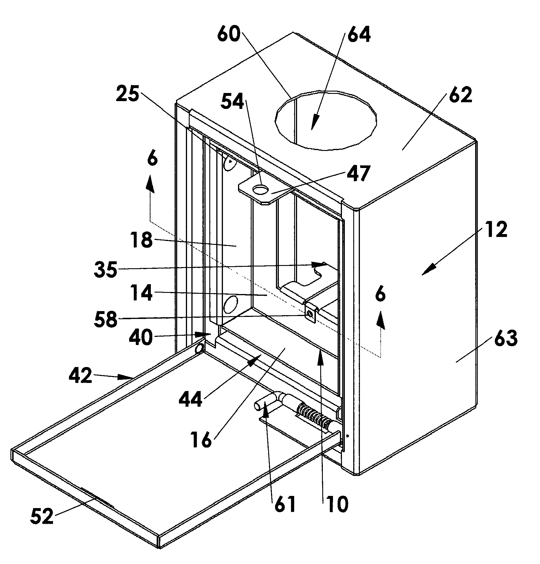
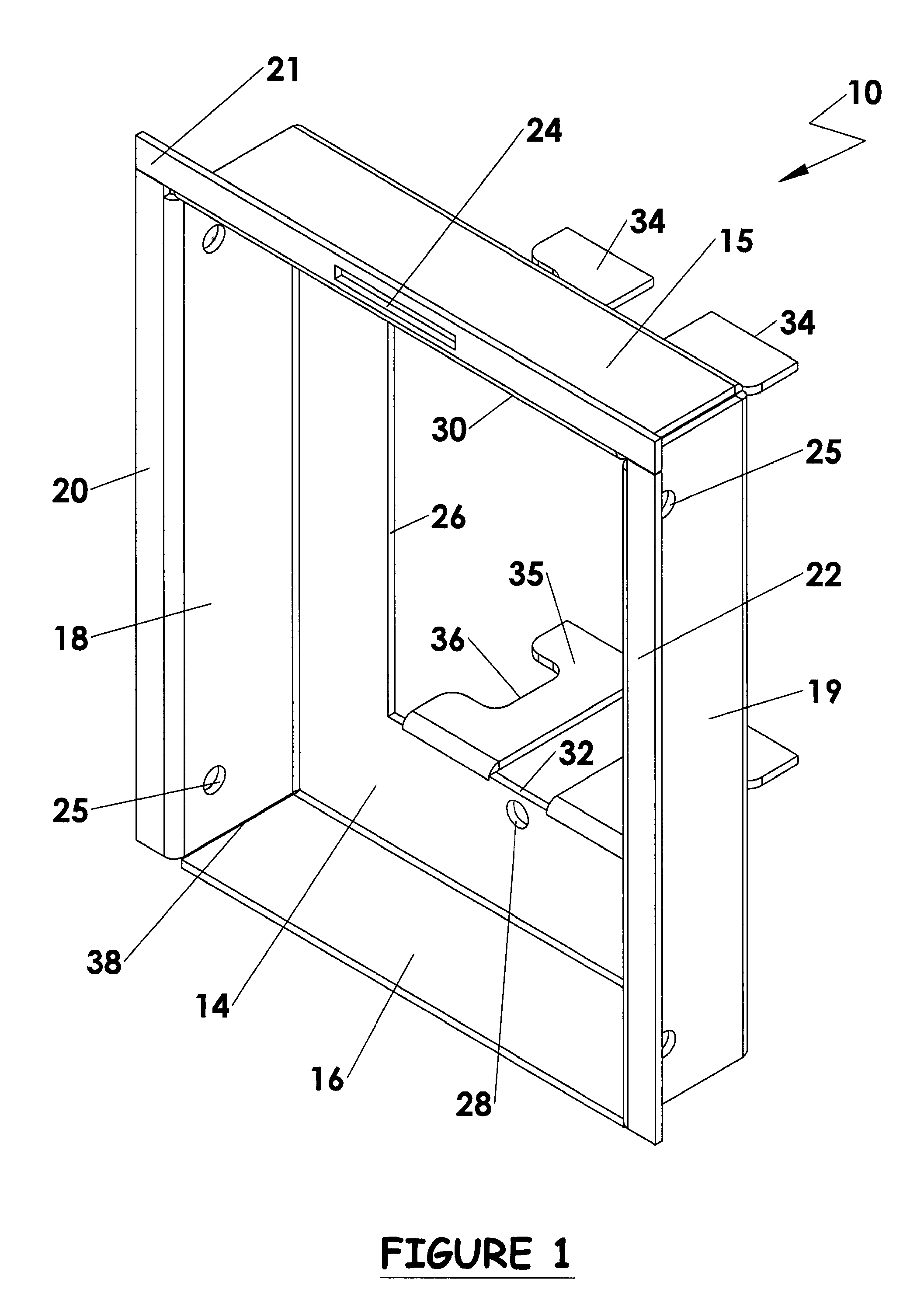
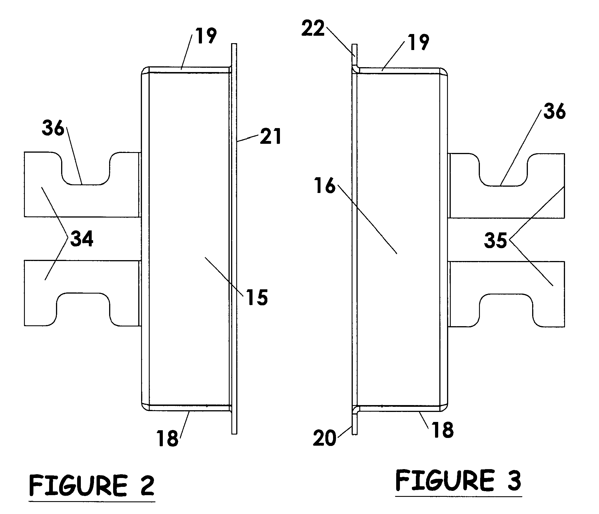
[0031]Certain embodiments as disclosed herein provide for a back plate device or face plate connector insert designed for mounting in a locked enclosure or user control box of a secure conduit or network system, the device having a recessed mounting face or back plate for mounting an electrical connector face plate to which authorized users having access to the box can connect authorized appliances such as computers, communication devices, and the like.

[0032]After reading this description it will become apparent to one skilled in the art how to implement the invention in various alternative embodiments and alternative applications. However, although various embodiments of the present invention will be described herein, it is understood that these embodiments are presented by way of example only, and not limitation. As such, this detailed description of various alternative embodiments should not be construed to limit the scope or breadth of the present invention as set forth in the a...


PUM


Abstract

A back plate device is formed by a generally rectangular frame having an open front face a back plate which is recessed inwardly from the open front face, and at least one wall extending forward from the back plate to the open front face, the wall extending around at least part of the frame periphery. The back plate has a cable access opening and a ledge surrounding the opening against which a face plate can be seated. The outer dimensions of the frame are less than the inner dimensions of a network connection box in which it is to be mounted, and the back plate is spaced from a rear wall of the box when installed to define a concealed cable management area behind the frame.

Description

RELATED APPLICATIONS[0001]The present application claims the benefit of co-pending U.S. provisional patent application No. 61 / 030,067 filed Feb. 20, 2008, which is incorporated herein by reference in its entirety.BACKGROUND[0002]1. Field of the Invention[0003]The present invention relates to a back plate device or face plate connector insert for a network connection box or enclosure in a network system which permits access for an authorized user to connect to the system.[0004]2. Related Art[0005]In many industries, there is a need for routing of signaling and transmission lines such as computer, power, communication and similar cables or wires. In some cases, access to such lines must be prevented or at least deterred. Secure conduit systems for this purpose are known and generally include one or more locked enclosures or control boxes to permit access and plug in to the system by authorized personnel, together with a secure conduit system which encloses the lines and extends betwee...

Claims


Application Information

Patent Timeline
Patent Type & Authority Applications(United States)
IPC IPC(8): H02G3/14
CPCH02G3/081H02G3/14H02G3/086Y10S248/906
Inventor MCCARTHY, CRAIG
Owner HOLOCOM
Why Eureka
Try Eureka