
Multi-meter test lead probe for hands-free voltage measurement of control panel industrial terminal blocks

a technology of industrial terminal blocks and test leads, which is applied in the direction of electrical testing, measurement devices, instruments, etc., can solve problems such as wacky situations, and achieve the effect of less strain on the terminal block

Inactive Publication Date: 2009-08-20
ARMSTRONG ERIC A
View PDF4 Cites 4 Cited by
  • Summary
  • Abstract
  • Description
  • Claims
  • Application Information

AI Technical Summary

Benefits of technology

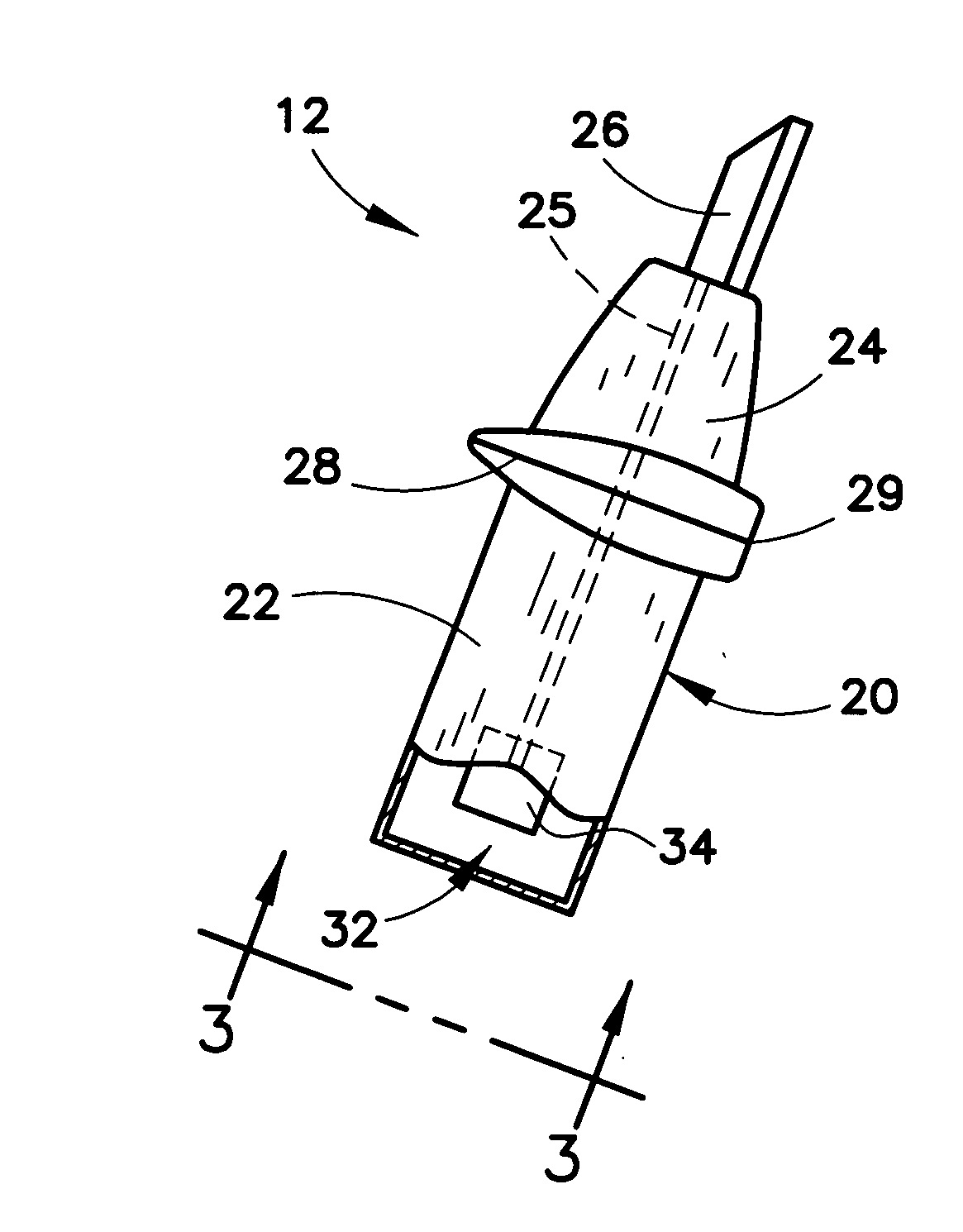
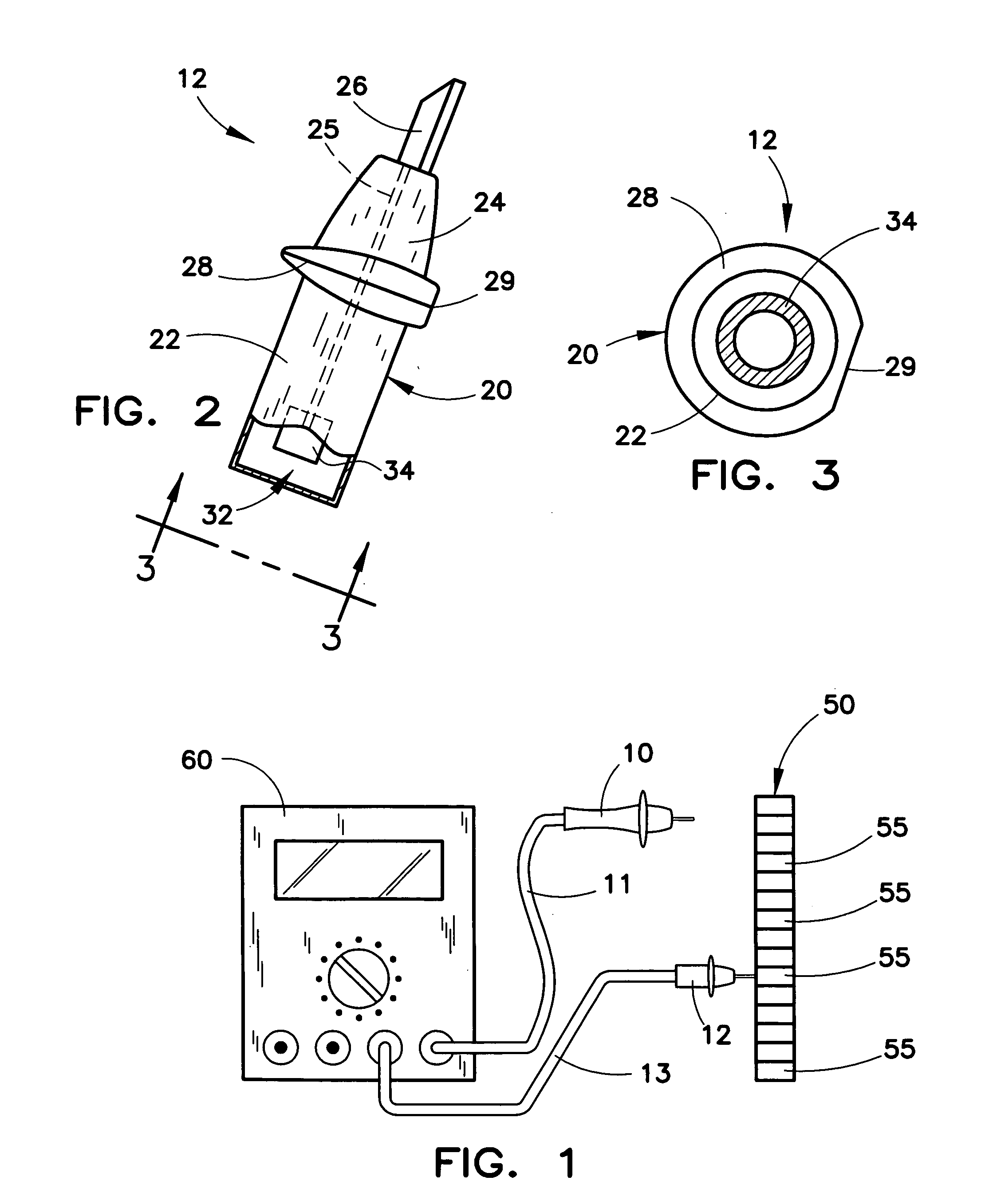
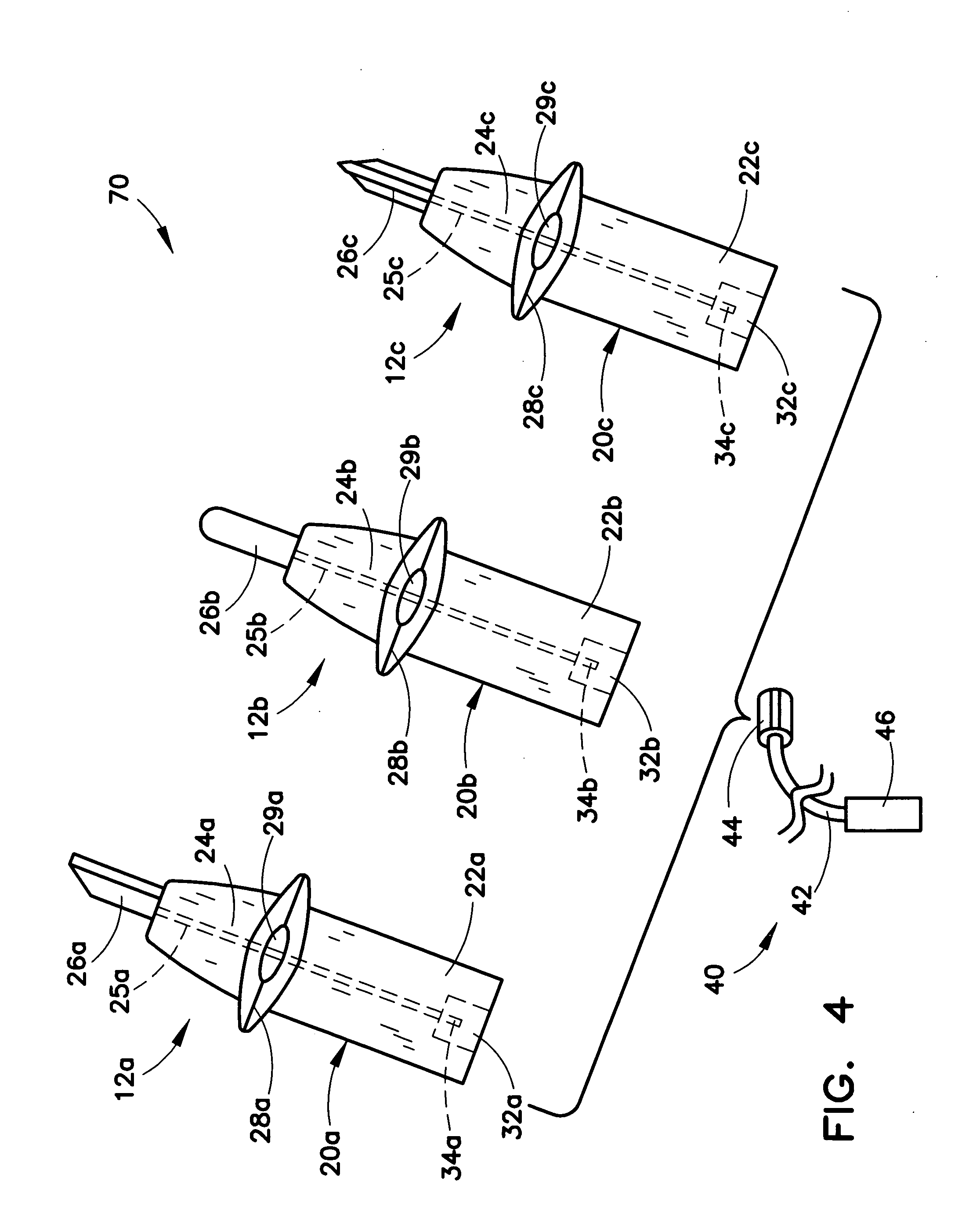
[0010]In the modular form of the present terminal block probe, a plurality of terminal block probes may be provided each one of which has an electrically conducting tip of a different configuration corresponding to different configurations and / or sizes of industrial terminal block sockets. In the case of multiple terminal block probes connectable to the modular multi-meter test lead, a terminal block probe kit is defined. Since there are multiple manufacturers of industrial terminal blocks, and each manufacturer uses different sizes of terminal blocks with different types and / or sizes of sockets, the use of a modular form of the present invention allows the user to easily take electrical measurements of various terminal blocks. Moreover, in the modular form, if two terminal block probes of the present invention are used on both ends of the multi-meter test lead, the test lead may be used as a jumper between terminal blocks.
[0013]The shortened configuration of the body of the present control panel terminal block probe provides less strain on a terminal block than present multi-meter probes.

Problems solved by technology

This can create an awkward situation.

Method used


Image

  • Multi-meter test lead probe for hands-free voltage measurement of control panel industrial terminal blocks
  • Multi-meter test lead probe for hands-free voltage measurement of control panel industrial terminal blocks
  • Multi-meter test lead probe for hands-free voltage measurement of control panel industrial terminal blocks

Examples


Embodiment Construction

[0022]Referring to FIG. 1, there is shown a digital multi-meter (DMM) generally designated 60 used to take voltage measurements of industrial terminal blocks 55 of an industrial control panel 50. A first electrical test lead 11 is shown plugged into a positive voltage receptacle of the DMM 60 and may be considered a positive test lead, while a second test lead 13 is shown plugged into a negative, neutral or ground voltage receptacle of the DMM 60 and may be considered a negative, neutral or ground test lead (hereinafter collectively, neutral test lead). A conventional test lead probe 10 is attached to the positive test lead 11 and is adapted to be held by a user (e.g. an engineer or technician) and held in contact with a positive terminal or contact of one of the industrial terminal blocks 55 during a voltage measurement thereof. A terminal block probe and especially but not necessarily an industrial terminal block probe 12 (collectively hereinafter, an industrial terminal block pro...


PUM


Abstract

An electrical test lead probe for use with a multi-meter provides for releasable retention in and electrical contact with a terminal of an industrial terminal block. The test lead probe includes a shortened body having an electrically conducting tip that is configured for releasable receipt into a terminal block socket of an industrial terminal block, the terminal block socket housing a terminal of the terminal block. The present terminal block probe, in one form, is permanently attached to a multi-meter test lead. In another form, the present terminal block probe is coupled to a modular multi-meter test lead. In yet another form, the present terminal block probe has a removable head incorporating an electrically conducting tip wherein the body is permanently attached to a multi-meter test lead. In a modular form, a plurality of terminal block probes may be provided each one of which has an electrically conducting tip of a different configuration corresponding to different configurations and / or sizes of industrial terminal block sockets.

Description

BACKGROUND OF THE INVENTION[0001]1. Field of the Invention[0002]The present invention relates to equipment for taking electrical measurements of electrical circuits, components and / or devices and, more particularly, to multi-meter test lead probes for voltage measurement of control panel industrial terminal blocks.[0003]2. Background Information[0004]Industrial control systems use control panels to host electrical components that allow manufacturing processes to be automated. A common component among control panels is the industrial terminal block. Industrial terminal blocks have several uses within a control panel, but are used primarily to provide termination points between field devices and components within the industrial control panel. During system startup or troubleshooting, automation engineers and technicians use multi-meters such as digital multi-meters (DMMs) to take voltage readings at these industrial terminal blocks to help solve issues with the automated system.[0005]...

Claims


Application Information

Patent Timeline
Patent Type & Authority Applications(United States)
IPC IPC(8): G01R1/06
CPCG01R1/06788
Inventor ARMSTRONG, ERIC A.
Owner ARMSTRONG ERIC A
Learn More