
Cec control apparatus

a control apparatus and cec technology, applied in the direction of program control, electric programme control, television system, etc., can solve the problems of limited lack of versatility in the overall control of cec devices, and limited consumer choi

Inactive Publication Date: 2009-08-20
SMK CORP
View PDF1 Cites 37 Cited by
  • Summary
  • Abstract
  • Description
  • Claims
  • Application Information

AI Technical Summary

Benefits of technology

[0033]In another embodiment, CEC control apparatus, for acquiring CEC control information, corresponding to the CEC device to be controlled that has been stored in the control information storage part based on the acquired vendor code and the received control signal, provides:
[0066]Moreover, with the provision of this CEC control apparatus in a personal computer PC or the like, even if CEC controllable home electronics products are replaced, familiar operations can be performed with the same remote controller as had been used previously.

Problems solved by technology

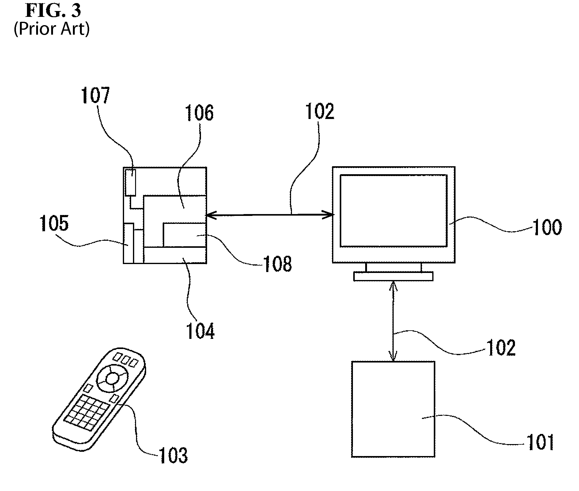
However, with the conventional control of a CEC device, only CEC control information corresponding to the vendor of the CEC device to which the receiver unit 104 is attached is stored in the storage means 107, and CEC device control is thereby limited to devices from the same vendor, i.e., devices from the same manufacturer and same series.
As a result, versatility is lacking in the overall control of CEC devices.
Accordingly, a consumer is also limited to the same manufacturer and same series when purchasing a CEC device.
Control of CEC devices from different manufacturers has been difficult to implement with a receiver unit 104 associated with a different CEC device.
Similarly, in after some period of time, there was a problem in that even if a newly-purchased device is from the same manufacturer, the CEC control device commands may not correspond to the vendor, and device control becomes difficult to implement.
Even in this case, the device commands will end up corresponding to the vendor of the personal computer PC, and versatility in the CEC device control cannot be achieved.

Method used


Image

  • Cec control apparatus
  • Cec control apparatus
  • Cec control apparatus

Examples


embodiment 1

[0071]Embodiments of the present invention are described below with reference to drawings.

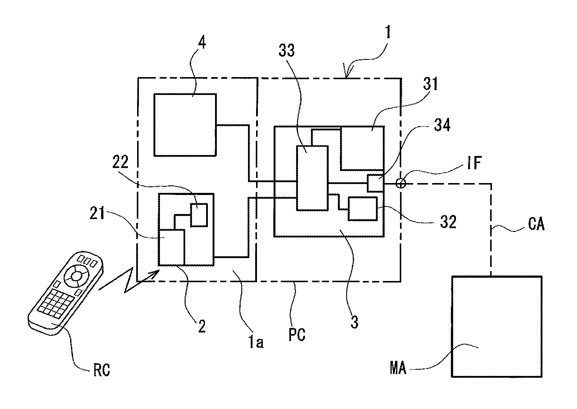
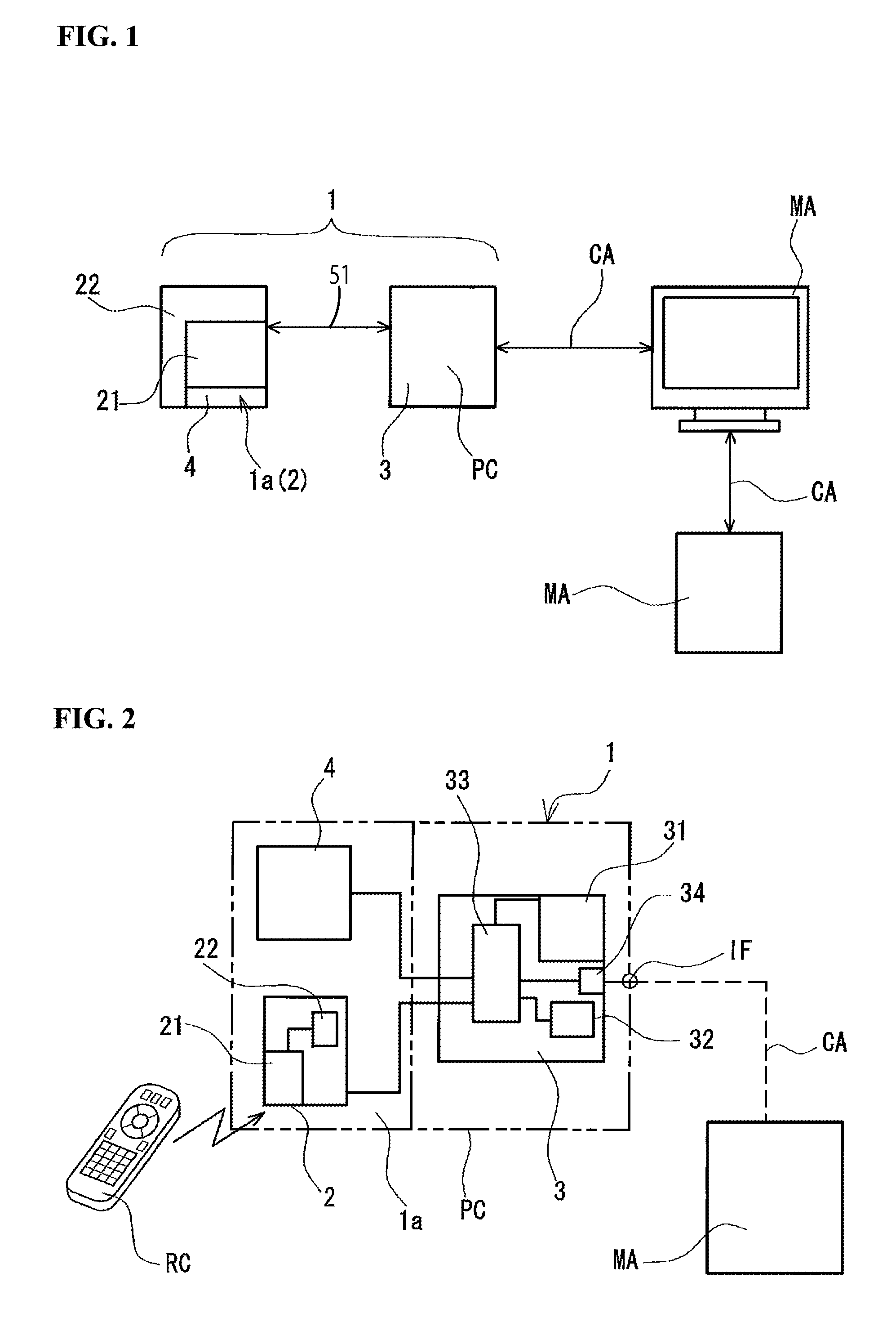
[0072]Reference numeral 1 denotes a CEC control apparatus, which represents an embodiment of the present invention. As shown in FIG. 1, the CEC control apparatus 1 is externally connected via a USB connection 51 to a personal computer PC so as to be coupled with the personal computer PC, and is formed as an apparatus for controlling a CEC device MA. Furthermore, in the description of this embodiment, the function of the personal computer PC for operating in accordance with an OS and application software is already known and therefore is not described herein, but the functions provided to devices, connected externally or connected to the motherboard, for operating in accordance with the CPU, memory, hard disk, display, various interfaces and the like provided in the PC are demonstrated, and coupled with the personal computer PC, these functions perform various processes. Accordingly, the CEC con...


PUM


Abstract

A Consumer Electronics Control (CEC) control apparatus includes a vendor code acquisition instruction unit that queries a CEC device for a vendor code when connected to a CEC device, a control part provided with a storage unit capable of storing the reference location of stored CEC control information that corresponds to the acquired vendor code, a control information storage part which, for each vendor, pre-stores CEC control information corresponding to a plurality of vendors, and a photoreceptor unit having a received signal demodulation unit capable of receiving a signal from a remote control RC and demodulating the signal to acquire a CEC control signal. Based on the acquired vendor information, the control part acquires from the control information storage part control information corresponding to the vendor corresponding to the control signal transmitted from the remote control RC, and outputs the CEC control signal to the externally connected CEC device.

Description

CROSS-REFERENCE TO RELATED APPLICATION[0001]This application claims the benefit under 35 U.S.C. §119 of Japanese Patent Application No. 2008-035994, filed on Feb. 18, 2008, which is hereby incorporated by reference herein in its entirety.FIELD OF THE INVENTION[0002]The present invention relates to a versatile CEC (Consumer Electronics Control) control apparatus that uses CEC commands to operate electronic products complying with high-definition multimedia standards.BACKGROUND OF THE INVENTION[0003]At present, a high-definition multimedia interface (hereafter simply referred to as HDMI) exists as a standard for controlling a wide variety of AV devices, such as LCD televisions, audio devices, and the audio and video recording devices connected thereto and used therewith.[0004]HDMI has already been standardized, and consumer electronics control (hereafter simply referred to as CEC) is one part of that standard (see, e.g., High-Definition Multimedia Interface Specification Version 1.3a,...

Claims


Application Information

Patent Timeline
Patent Type & Authority Applications(United States)
IPC IPC(8): G05B19/02H04N5/00H04N5/44H04N7/173H04Q9/00
CPCG08C2201/92G08C17/00
Inventor HAIJIMA, TOSHIO
Owner SMK CORP
Learn More