
Image processing device, projector, and distortion correction method

Active Publication Date: 2009-08-20
SEIKO EPSON CORP
View PDF1 Cites 23 Cited by
  • Summary
  • Abstract
  • Description
  • Claims
  • Application Information

AI Technical Summary

Benefits of technology

[0008]An advantage of some aspects of the invention is to prevent the processing load of the projector from increasing and improve the accuracy of distortion correction of the projection image.
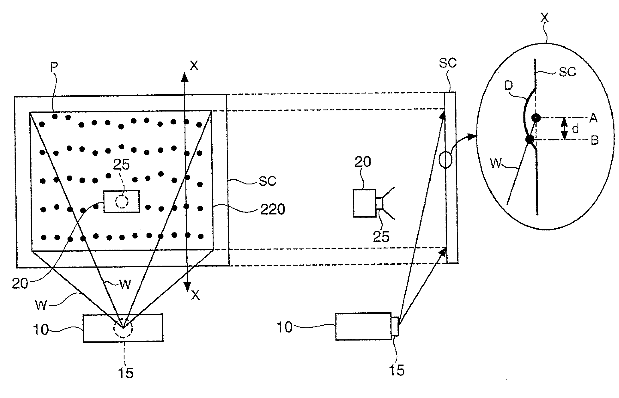
[0011]According to this aspect of the invention, since the distortion of the projection image is detected using the correction image data having predetermined figures arranged at densities varying in accordance with the incident condition of the projection light, the distortion amounts varying in accordance with the incident condition can be detected with good accuracy. Therefore, the distortion correction process with high accuracy can be executed on the image data representing the image projected on the projection screen. Therefore, it is possible to generate the image data for displaying an image without distortion on the projection screen. Further, according to the image processing device of this aspect of the invention, since the correction pattern formed to have a lower arrangement density of the predetermined figures in the position where the distortion amount of the projection image is thought to be small in accordance with the incident condition of the projection light, and to have a higher arrangement density of the predetermined figures in the position where the distortion amount of the projection image is thought to be large is used, the increase in the process load of the image processing device due to the increase in the number of the predetermined figures can be suppressed.
[0016]In the first aspect of the invention, the plurality of predetermined figures projected on the projection screen is arranged to have a higher density in accordance with a larger incident angle of the projection light to the projection screen. According to this aspect of the invention, the distortion in the position with a large incident angle of the projection light can be detected with good accuracy.
[0017]In the first aspect of the invention, the plurality of predetermined figures projected on a first position on the projection screen where the projection light enters at a first angle is arranged at a first density, and the plurality of predetermined figures projected on a second position on the projection screen where the projection light enters at a second angle larger than the first angle is arranged at a second density higher than the first density. According to this aspect of the invention, the distortion in the position with a large incident angle of the projection light can be detected with good accuracy compared to the position with a small incident angle of the projection light.
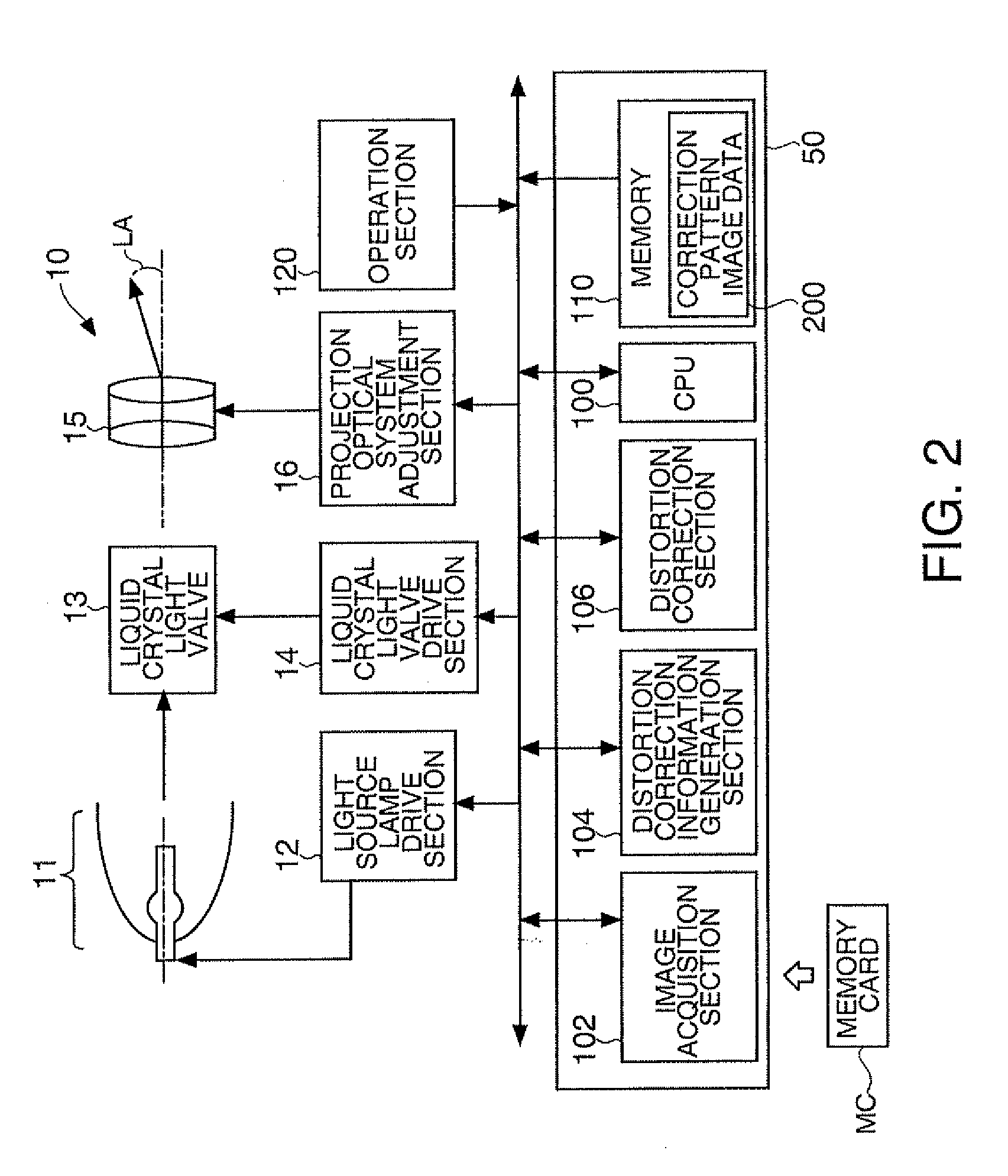
[0020]In the first aspect of the invention, a storage section adapted to previously store the correction image data corresponding to a configuration of an optical system of the projector is further provided. According to this aspect of the invention, the correction image data suitable for the projector has previously been stored. Therefore, since there is no need for generating the correction image data or acquiring the correction image data from another device, the process load of the projector can be reduced.

Problems solved by technology

Although the screen for the projectors is formed to have a planar shape, the shape is not a perfect plane, but has a slight bulge with a wrinkle or a slack caused by an installation environment, the temperature, the material of the screen, and aged deterioration.
In particular in a portable take-up screen, when carrying or retracting the screen, the pipe for retracting the screen is apt to creep to cause the wrinkle and the slack.
It is known that when projecting an image on the screen with the wrinkle or the slack is caused thereon, a distortion is caused in the image by the bulge derived from the wrinkle or the slack.
Therefore, in the case in which the pattern image with the dot figures arranged at the same intervals is used as in the related art, it is not achievable to detect the variation in the amount of distortion in accordance with the difference in the incident conditions of the projection light with high accuracy, and therefore, there is caused a problem that it is not achievable to correct the distortion of the image projected on the screen with high accuracy.
Further, in the case in which the pattern image having dot figures arranged thickly at the same intervals is used, the amount of distortion must be calculated as many times as the number of characteristic points, which increases the processing load of the projector, and incurs increase in the processing time.

Method used


Image

  • Image processing device, projector, and distortion correction method
  • Image processing device, projector, and distortion correction method
  • Image processing device, projector, and distortion correction method

Examples


second embodiment

B. Second Embodiment

[0064]In a second embodiment, the distortion correction process is executed using the correction pattern image having an arrangement with densities varying in accordance with the incident angle of the projection light. The projector 10 of the second embodiment is a short focus projector, and displays an image from a position below the projection screen SC and relatively near to the projection screen SC. It should be noted that in the second embodiment, the configuration of the projector and the flow of the distortion correction process are the same as in the first embodiment except the correction pattern image.

B1. Incident Angle and Correction Pattern Image

[0065]FIG. 7 is an explanatory diagram for exemplifying the incident angle of the projection light and the correction pattern image 300 in the second embodiment. The relationships between the incident angles of the projection light W2, W3 and the amounts of distortion of the projection image are respectively sh...

third embodiment

C. Third Embodiment

[0071]In a third embodiment, the distortion correction process is executed using the correction pattern image having an arrangement with a densities varying in accordance with the projection distance from the projector to a predetermined point of the projection screen SC. It should be noted that in the third embodiment, the configuration of the projector and the flow of the distortion correction process are the same as in the first embodiment except the correction pattern image. Further, the projection screen SC in the third embodiment has a lateral size larger than that of the projection screen SC in the first embodiment. Still further, the projector 10 of the third embodiment is a short focus projector, and displays an image from a position near to the projection screen SC.

C1. Projection Distance and Distortion of Projection Image

[0072]FIG. 8 is an explanatory diagram for explaining the projection distance of the projector 10b according to the third embodiment. ...

fourth embodiment

D. Fourth Embodiment

[0077]In the first through the third embodiments, the correction pattern image is previously stored in the storage device in the projector. In the fourth embodiment, the projector detects the tilt of the projector, and generates the correction pattern image in accordance with the tilt angle. It should be noted that in the fourth embodiment, the configuration of the projector and the flow of the distortion correction process are the same as in the first embodiment except that the distortion correction information generation section 104 is further provided with the function of generating the correction pattern image.

[0078]FIG. 10 is an explanatory diagram for explaining a tilt of a projector 10c in the fourth embodiment. The projector 10c has a projection lens designed so as to have the projection angle α in the condition in which the projector 10c is implemented on the horizontal plane. FIG. 10 shows the condition in which the projector 10c is tilted at an angle β...


PUM


Abstract

An image processing device adapted to correct distortion of an image projected on a projection screen with projection light emitted from a projector includes a detection section adapted to detect at least one of display positions of a plurality of predetermined figures displayed in a correction image projected by the projector on the projection screen, the plurality of figures arranged at densities varying in accordance with an incident condition of projection light to the projection screen, a distortion correction information generation section adapted to generate distortion correction information based on the display position detected and correction image data representing the correction image, an acquisition section adapted to acquire image data representing the image to be projected on the projection screen, and a distortion correction section adapted to execute a distortion correction process using the distortion correction information on the image data acquired.

Description

BACKGROUND[0001]1. Technical Field[0002]The present invention relates to image processing for a projector, and in particular to a distortion correction technology of an image displayed on a projection screen.[0003]2. Related Art[0004]There are used projectors adapted to project an image on a screen based on image data using an optical system, which is composed of various optical elements such as light valves, digital mirror devices, and a dichroic prism, and illumination light from a light source. Although the screen for the projectors is formed to have a planar shape, the shape is not a perfect plane, but has a slight bulge with a wrinkle or a slack caused by an installation environment, the temperature, the material of the screen, and aged deterioration. In particular in a portable take-up screen, when carrying or retracting the screen, the pipe for retracting the screen is apt to creep to cause the wrinkle and the slack.[0005]It is known that when projecting an image on the scree...

Claims


Application Information

Patent Timeline
IPC IPC(8): G09G5/00G03B21/14
CPCH04N9/3185H04N9/3197H04N9/3194
Inventor FURUI, SHIKIIMAI, SHUN
Owner SEIKO EPSON CORP
Learn More