Switch network system, controller, and control method

Inactive Publication Date: 2012-01-26
NEC CORP
View PDF3 Cites 63 Cited by
  • Summary
  • Abstract
  • Description
  • Claims
  • Application Information

AI Technical Summary

Benefits of technology

[0019]According to the present invention, it is possible to prevent excessive traffic flow into the controller when controlling the flow table of the switch. As a resul

Problems solved by technology

However, in the case where packets are transmitted from the desired switch to the controller, a large amount of traffic may flow into the controller.
Therefore, if the switch forwards a large amount of traffic to the controller, the controller side cannot afford to h

Method used


Image

  • Switch network system, controller, and control method
  • Switch network system, controller, and control method
  • Switch network system, controller, and control method

Examples


Example

[0035]Exemplary embodiments of the present invention will be described below with reference to the attached drawings.

[0036]1. Configuration

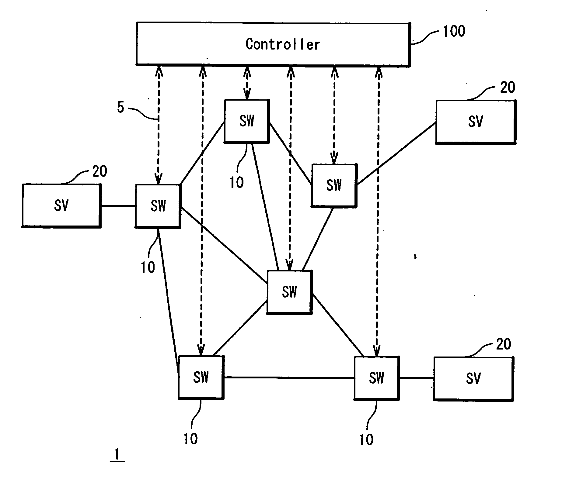
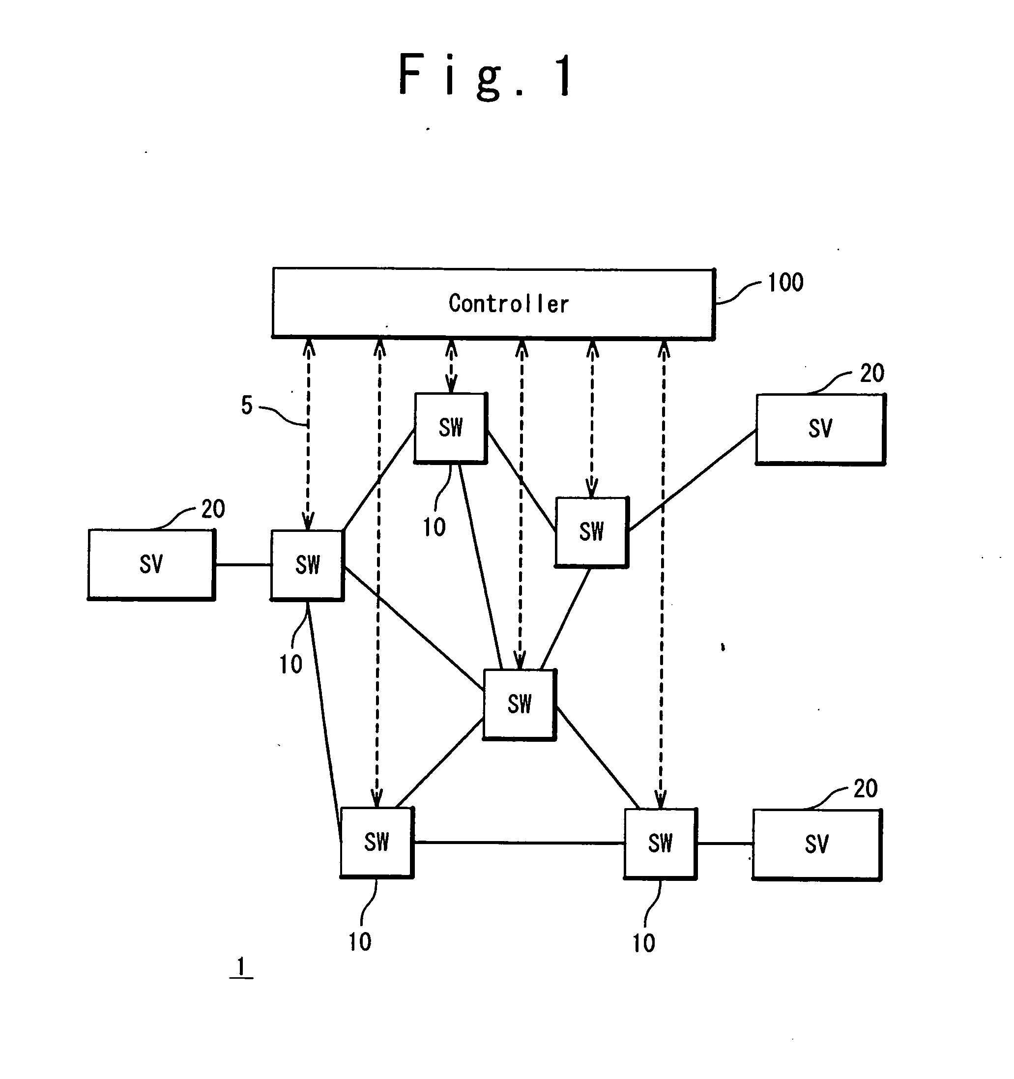
[0037]FIG. 1 is a block diagram showing a configuration example of a switch network system 1 according to the present exemplary embodiment. The switch network system 1 has switches 10, servers 20 and a controller 100. The plurality of switches 10 are arranged in a network in a distributed manner. The switches 10 are connected by links (lines) to each other, and thus a switch network is configured by the plurality of switches 10. The switch network lies between the plurality of servers 20.

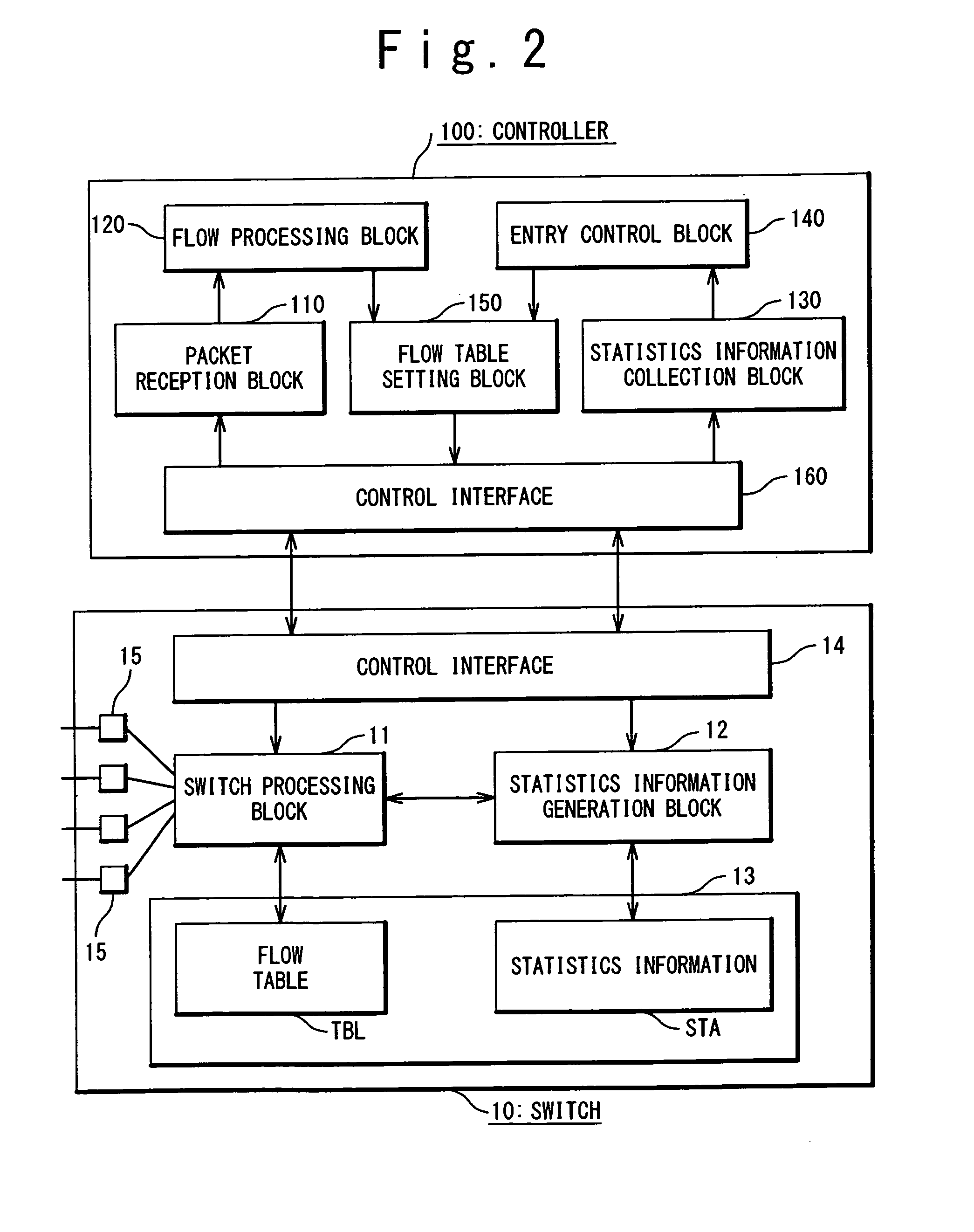
[0038]Each of the switches 10 has a flow table and performs packet processing in accordance with the flow table. It is the controller 100 that controls the flow table. The controller 100 is connected to the switches 10 through control links 5 and has a function of setting the flow table of each switch 10 through the control link 5. The controller 100 can appropri...


PUM


Abstract

A controller has an entry control block and a flow table setting block. In a case where an action of a target entry in a flow table is to be changed to “forwarding of a reception packet to the controller”, the entry control block forecasts a load when packets matching the target entry are forwarded to the controller. If the load exceeds a permissible value, the entry control block repeats entry division processing until the load becomes within the permissible value. In the entry division processing, the entry control block divides the target entry into a plurality of post-division entries, divides the match condition of the target entry into a plurality of conditions, and sets respective match conditions of the plurality of post-division entries to the plurality of conditions. The flow table setting block instructs a switch to set the plurality of post-division entries in the flow table.

Description

CROSS-REFERENCE TO RELATED APPLICATION[0001]This is a continuation of International Application No. PCT / JP2010 / 072954, filed on Dec. 21, 2010.TECHNICAL FIELD[0002]The present invention relates to a technique that controls a switch network system including a switch and a controller.BACKGROUND ART[0003]Non-Patent Literature 1 (Nick McKeown et al., “Open Flow: Enabling Innovation in Campus Networks”, ACM SIGCOMM Computer Communication Review, Vol. 38, No. 2, 2008. (http: / / www.openflowswitch.org / / documents / openflow-wp-latest.pdf)) describes a technique called “Open Flow”. In the Open Flow, route control, failure recovery, load distribution and optimization are performed on an individual flow basis. In the Open Flow, an open flow switch serving as a forwarding node and an open flow controller controlling the open flow switch are used.[0004]The open flow switch is provided with a flow table that indicates a correspondence relationship between a “match condition” and an “action”, and opera...

Claims


Application Information

Patent Timeline
IPC IPC(8): H04L12/56H04L45/42
CPCH04L49/50H04L47/127
Inventor UENO, HIROSHI
Owner NEC CORP
Why Eureka
Try Eureka