Display device

Active Publication Date: 2009-08-20
DAWNCREST IP LLC
View PDF3 Cites 12 Cited by
  • Summary
  • Abstract
  • Description
  • Claims
  • Application Information

AI Technical Summary

Benefits of technology

[0019]According to the present invention, the mechanical bonding strength can be enhanced and the deteri

Problems solved by technology

However, along with the achievement of the thinner liquid crystal display devices, the LCD 62 has become more fragile due to dropping of portable devices onto which the liquid crystal display device is mounted or due to objects fallen onto a display surface of the LCD 62.
In addition, there has been a risk that, when an air space is interposed between the LCD 62 and the translucent substrate 68, light may be reflected on the display surface of the LCD 62 or a lower surface of the translucent substrate 68, and hence the display surface becomes dark due to this reflection loss.
A heat curing adhesive which is cured by heat may be used, but is difficult to use because, for example, liquid crystals or polarizing plates are deteriorated when the heat curing adhesive is exposed to a high temperature equal to or higher than 100 degrees, or shelf life of the adhesive is short.
H

Method used


Image

  • Display device
  • Display device
  • Display device

Examples


Embodiment Construction

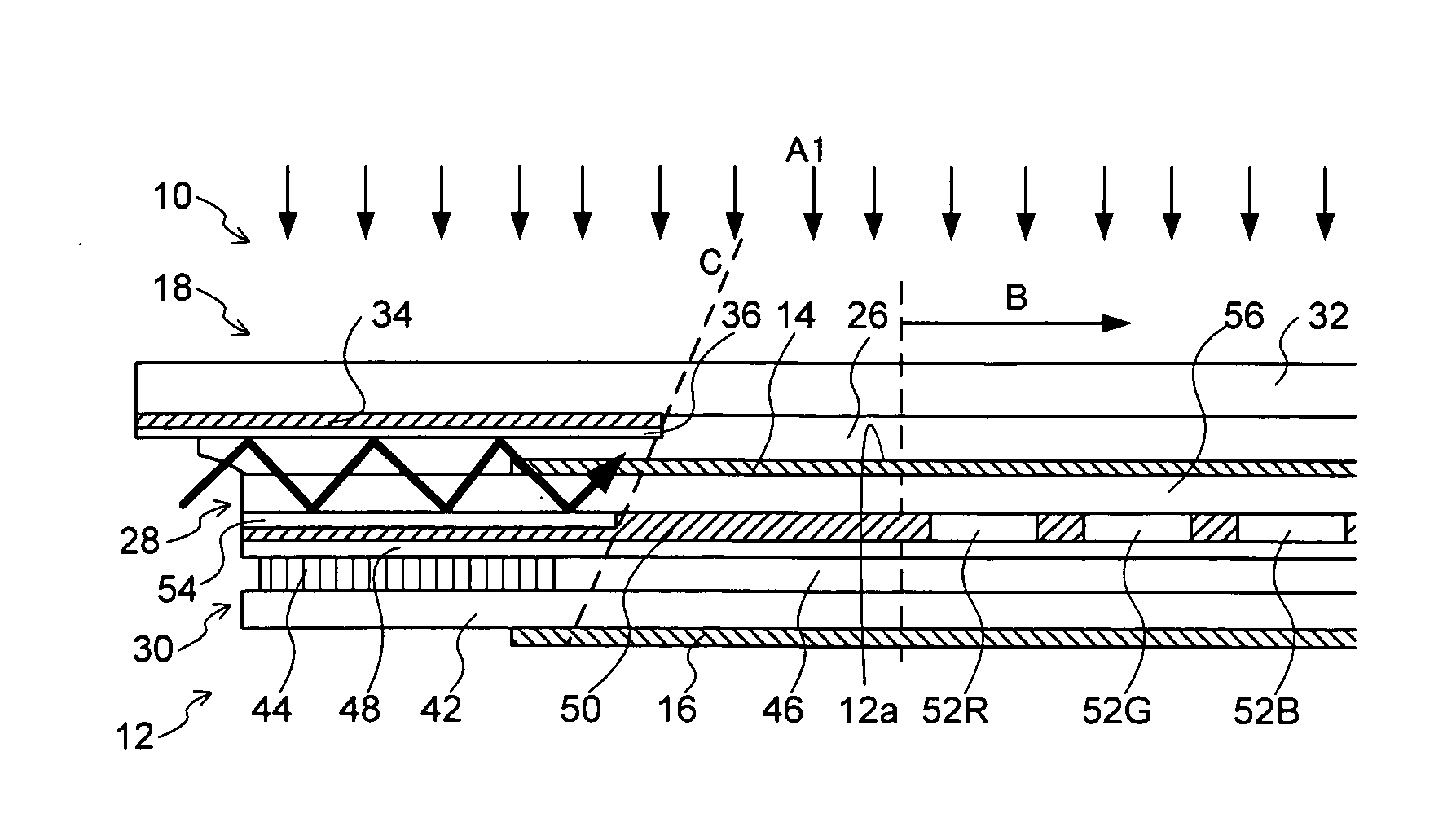
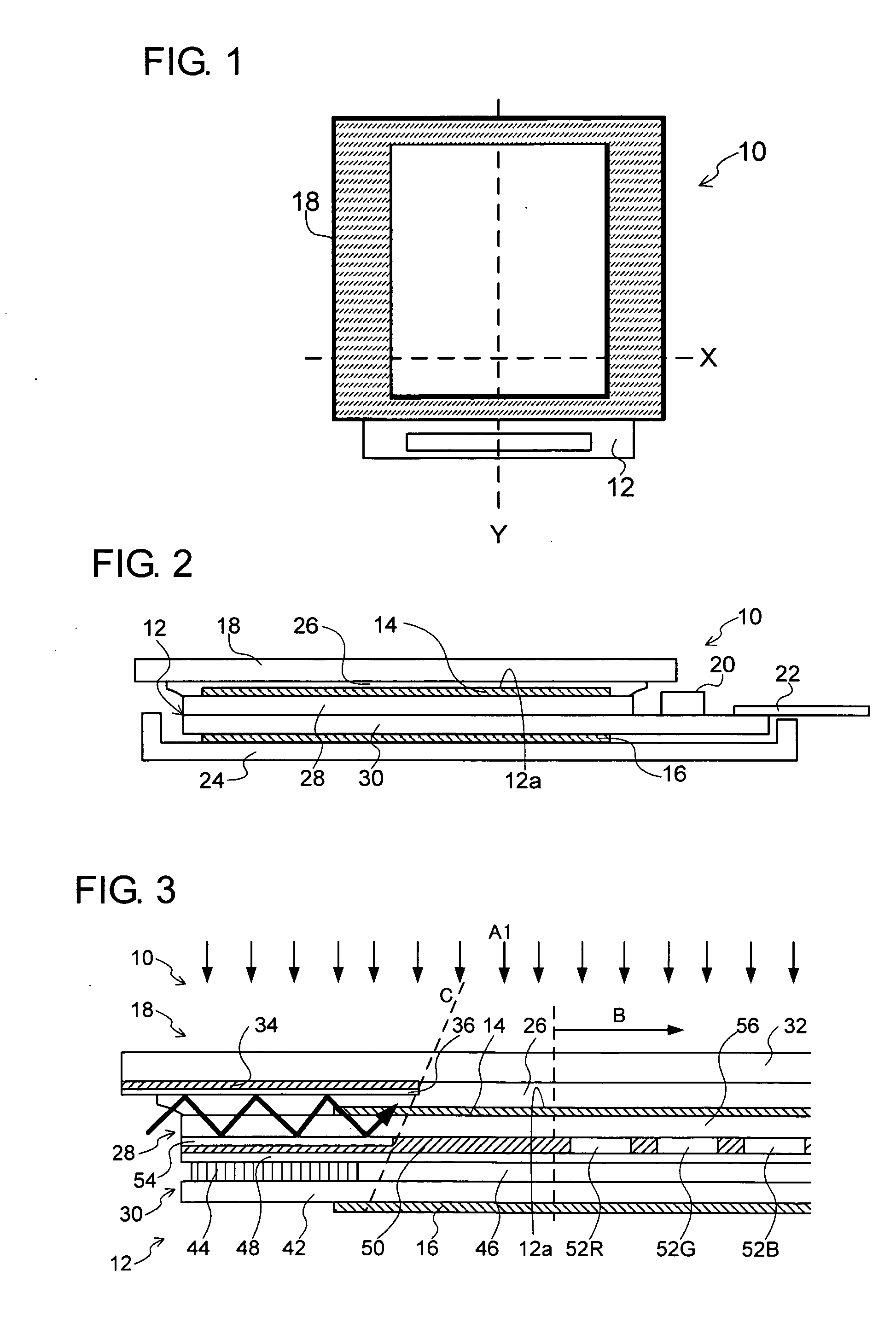
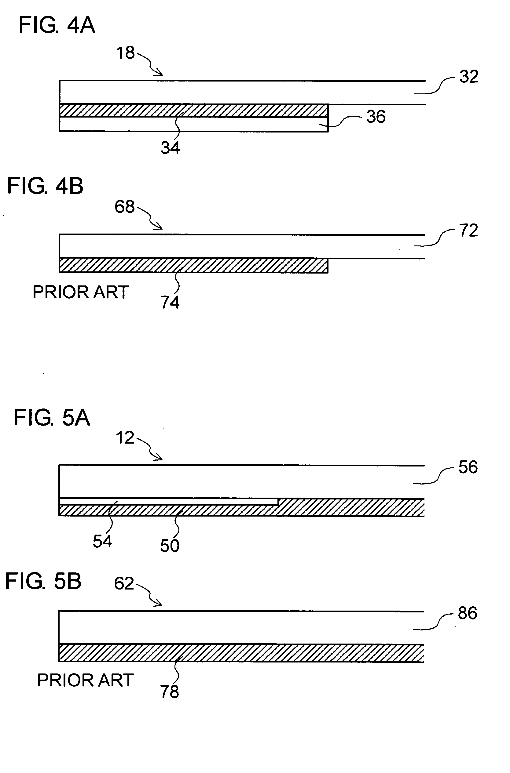
[0032]In the present invention, a display device includes a display panel and a translucent substrate for transmitting light. The display panel has a display surface on which an image is displayed. The translucent substrate is provided so as to be opposed to the display surface. A light shielding portion for intercepting light is provided on a periphery of the translucent substrate. A photo-curable translucent adhesive exists between the display panel and the translucent substrate in order to integrally bond to each other. A light reflecting portion is provided on a display surface side of the light shielding portion. With this structure, the translucent adhesive of the light shielding portion is brought into contact with the light reflecting portion. Accordingly, light for curing the translucent adhesive is prevented from being absorbed in the light shielding portion, and hence an uncured portion of the translucent adhesive can be reduced in the light shielding portion.

[0033]Furthe...


PUM


Abstract

In a case of curing and bonding a liquid crystal display panel (LCD) and a translucent substrate by using an optical adhesive, in order to reduce bonding fluctuations occurring in the vicinity of a light shielding portion provided on a periphery of the translucent substrate, enhance mechanical bonding strength, and prevent deterioration of image quality, which arises from curing variations of the optical adhesive, there is provided a display device including: a display panel including a display surface; a translucent substrate opposed to the display surface; a light shielding portion provided on a periphery of a display surface side of the translucent substrate, for shielding light; and a light reflecting portion provided on a display surface side of the light shielding portion.

Description

BACKGROUND OF THE INVENTION[0001]1. Field of the Invention[0002]The present invention relates to a display device using a display panel. In particular, the present invention relates to a display device having a structure in which a translucent substrate including a light shielding portion formed on a periphery of a display surface side is bonded to a display panel.[0003]2. Description of the Related Art[0004]A liquid crystal display device (LC display device) is used in various devices such as a cellular phone, a personal digital assistant (PDA), an electronic dictionary, a car navigation system, and a music player. FIGS. 6A and 6B illustrate a conventionally-known liquid crystal display device. FIG. 6A is a plan view and FIG. 6B is a longitudinal sectional view. As illustrated in FIGS. 6A and 6B, the liquid crystal display device includes a liquid crystal display panel (LCD) 62 and a translucent substrate 68 thereabove, which serves as a front plate. In the LCD 62, a liquid crystal...

Claims


Application Information

Patent Timeline
IPC IPC(8): G02F1/1333
CPCG02F2001/133388G02F1/133512G02F1/133388
Inventor IIDA, HARUHISA
Owner DAWNCREST IP LLC
Why Eureka
Try Eureka