Light source system, light source device, and method of controlling light source

a light source and light source technology, applied in the direction of instruments, electric lighting, lighting and heating apparatus, etc., can solve the problems of untrue, extremely poor operation efficiency, and brightness, and achieve local enhancement, local enhancement, and local enhancement

Inactive Publication Date: 2009-08-20
SONY CORP
View PDF8 Cites 9 Cited by
  • Summary
  • Abstract
  • Description
  • Claims
  • Application Information

AI Technical Summary

Benefits of technology

[0009]In view of foregoing, it is desirable to provide a light source system, a light source device, and a light source control method, which may locally increase light intensity in light intensity distribution without increasing number of light sources or drive current.
[0015]According to the light source system, the light source device, and the light source control method according to an embodiment of the invention, a diffusion unit varies diffusibility in incident light so that light intensity in a light intensity distribution in a plane, resulted from light emitted from the light source, is locally enhanced. Therefore, a light intensity distribution is locally enhanced without increasing a number of light sources and drive current.

Problems solved by technology

However, in case that the region is to be brightened, a brightening degree is limited due to a limit of efficiency of a light source, and a limit of a light source element.
That is, 50% of maximum light-quantity generation capability is constantly used during normal operation, resulting in extremely bad operation efficiency in an economical sense.
However, in case that a screen is partially brightened, this is not true from the above circumstances.
However, for example, when a backlight is designed using a necessarily sufficient number of light sources to achieve required luminance during whole white display, further brightening of a backlight by flowing a further larger current may not be performed because of over-rating.
This is the reason for the fact that 50% of maximum light-quantity generation capability is constantly used during normal operation, resulting in extremely bad operation efficiency in an economical sense.
In this way, while a backlight can be conceptually partially brightened, the concept is actually hardly practiced due to the economical circumstances as an obstacle.

Method used


Image

  • Light source system, light source device, and method of controlling light source
  • Light source system, light source device, and method of controlling light source
  • Light source system, light source device, and method of controlling light source

Examples


first embodiment

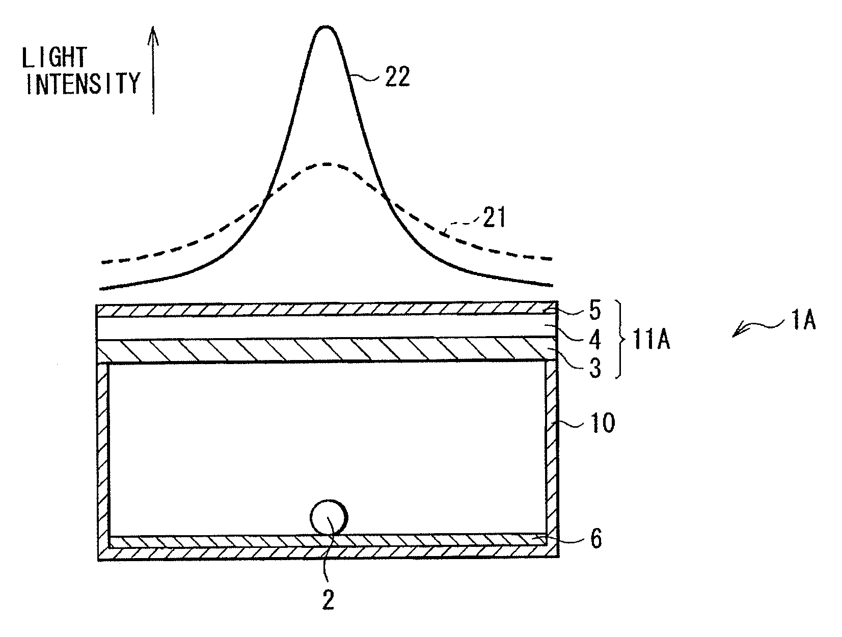
[0030]FIG. 1 shows a configuration example of a light source system according to a first embodiment of the invention together with an example of light intensity distribution in the system. In the embodiment, a configuration example of an illumination device 1 is described as a light source system. The illumination device 1 has a light source 2 disposed via a reflection seat 6 in the center of a bottom of a housing 10, and a diffusion section 11 disposed at an upper side (light emission side) of the housing 10. The light source 2 is configured by, for example, white LED. A plurality of light sources 2 may be provided.

[0031]The diffusion section 11 corresponds to a specific example of the “diffusion unit” of the invention. The illumination device 1 corresponds to a specific example of the “light source device” of the invention.

[0032]The diffusion section 11 is configured by stacking a plurality of sheet-like optical members. Specifically, a diffusibility variable element 4 configured ...

second embodiment

[0045]Next, a second embodiment of the invention is described. Substantially the same components as in the first embodiment are marked with the same symbols, and description of them is appropriately omitted.

[0046]The embodiment relates to a configuration example in case that the illumination device 1 according to the first embodiment is applied to a backlight of a display apparatus. FIG. 8 shows an example of a display apparatus as a light source system according to the embodiment. The display apparatus is a transmission liquid crystal display apparatus, and includes a backlight 60 and a liquid crystal panel 70. The liquid crystal panel 70 is a display section that uses illumination light from the backlight 60 to display a picture according to an input video signal Vin, and has a function of modulating the illumination light based on the input video signal Vin. The backlight 60 may include a diffusion section 62 in addition to a light source section 61.

[0047]FIG. 9 shows a configura...


PUM


Abstract

Light intensity may be locally increased in light intensity distribution without increasing number of light sources or drive current. A light source system includes a light source, and a diffusion unit varying diffusibility in incident light so that light intensity in a light intensity distribution in a plane, resulted from light emitted from the light source, is locally enhanced.

Description

CROSS REFERENCES TO RELATED APPLICATIONS[0001]The present invention contains subject matter related to Japanese Patent Application JP 2008-039129 filed in the Japanese Patent Office on Feb. 20, 2008, the entire contents of which being incorporated herein by reference.BACKGROUND OF THE INVENTION[0002]1. Field of the Invention[0003]The present invention relates to a light source system, a light source device, and a method of controlling a light source, which may control luminance distribution of light from a light source.[0004]2. Background Art[0005]A light source using a rod-like fluorescent tube such as CCFL (Cold Cathode Fluorescent Lamp) has been known as, for example, a light source of a backlight of a liquid crystal display apparatus. Moreover, a backlight has been proposed, in which a rod-like ultraviolet lamp is used as a light source, and ultraviolet rays are converted into visible light for illumination light (refer to Japanese Unexamined Patent Application, Publication No. ...

Claims


Application Information

Patent Timeline
Patent Type & Authority Applications(United States)
IPC IPC(8): F21S6/00
CPCG02F1/133603G02F2001/133607G09G3/3426G09G3/3611G09G2360/145G09G2320/064G09G2320/0646G09G2320/066G09G2320/0285G02F1/133607
Inventor FURUKAWA, NORIMASASHIMIZU, JUN
Owner SONY CORP
Why Eureka
Try Eureka