Electric power converter system with parallel units and fault tolerance

Active Publication Date: 2014-10-23
INGETEAM POWER TECH
View PDF2 Cites 6 Cited by
  • Summary
  • Abstract
  • Description
  • Claims
  • Application Information

AI Technical Summary

Benefits of technology

[0015]Therefore, there is the need of an electric energy conversion system with a greater availability and smaller space requirements, capable of being adapted to the failure situations of

Problems solved by technology

When a failure occurs, i.e., when a conversion unit stop being operative (for example, because at least one of its conversion modules fails) and is not capable of generating the output current required therefrom, the maximum power which the system is capable of generating in entirety declines by a factor of 1/N.
However, if the number of conversion units for reducing said factor of 1/N is increased, the complexity of the system as well as its cost and the space necessary for installing it is increased.
Likewise, the probability that a failure occurs in any of the conversion units is increased.
Particularly, the requirements of high-power conversion systems with an improved availability have increased considerably due to the boom of the new offshore wind energy generation locations in which the problem due to the difficulty of maintaining them and the great loss of energy involving the lack of availability thereof is increased.
This solution therefore involves increasing the number of conversion units of the system which has the clear drawback of involving an increased complexity, cost

Method used


Image

  • Electric power converter system with parallel units and fault tolerance
  • Electric power converter system with parallel units and fault tolerance
  • Electric power converter system with parallel units and fault tolerance

Examples


Embodiment Construction

[0044]In this text, the term “comprises” and its derivations (such as “comprising”, etc.) must not be interpreted in an excluding manner, i.e., these terms must not be interpreted as excluding the possibility that what is described and defined may include other elements, steps, etc.

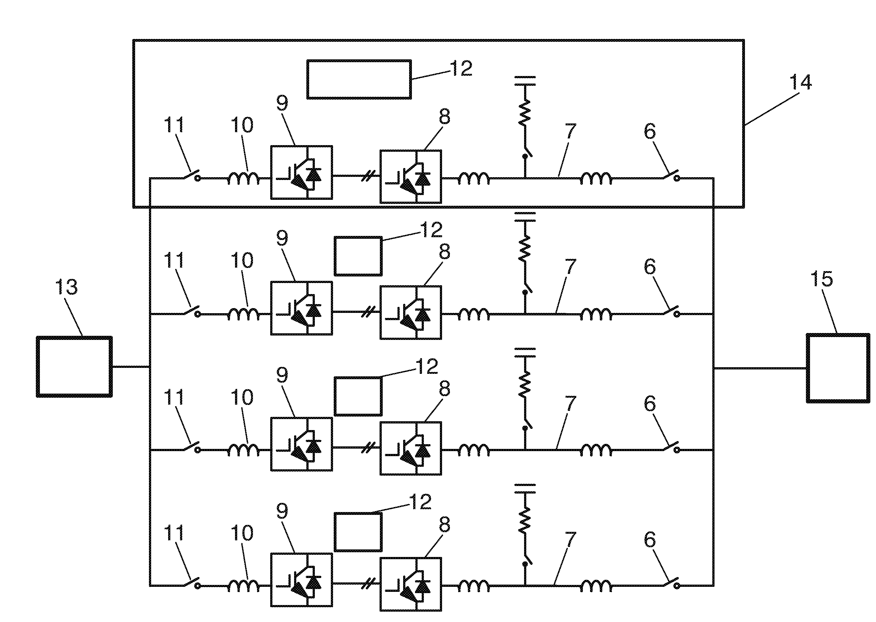
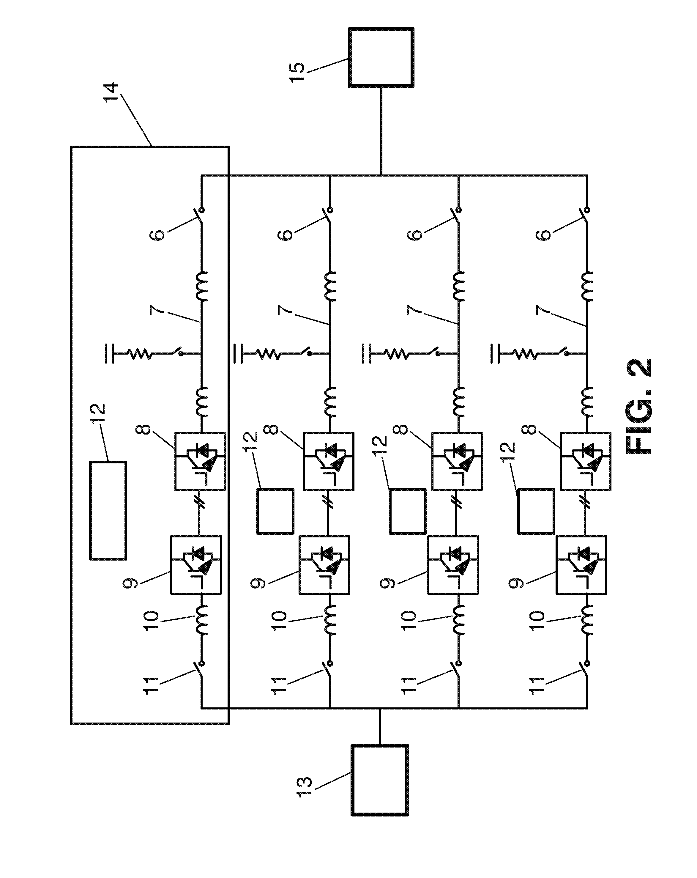
[0045]Likewise, it should be noted that, despite the fact that the detailed description of the invention is made according to a series of preferred embodiments with a determined number of conversion units and with certain characteristics of the input and output voltage of the system, the latter is valid for any other number of conversion units, as well as for any other input and output configuration of the system.

[0046]In addition, it must be understood that when speaking of a coolant (for example, water) in this invention it is not limited exclusively to fluid cooling conversion systems rather the concept must be extrapolated to systems which may be air cooling system.

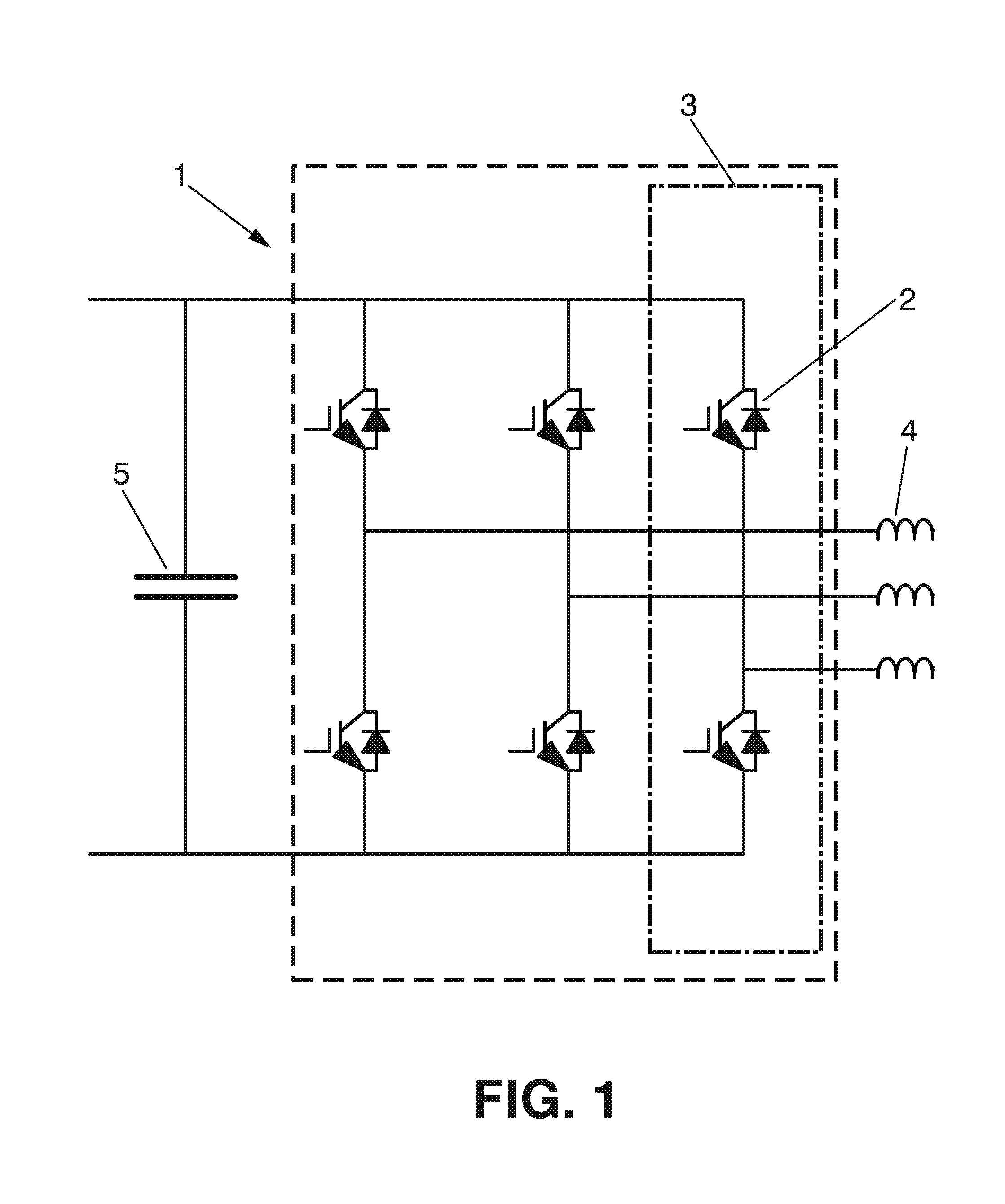
[0047]FIG. 1 shows a conventional el...


PUM


Abstract

The present invention relates to an electric energy conversion method and system with at least two conversion units (14), comprising control means (12) establishing the maximum output current of the operative conversion modules, as well as the commutation frequency of the entire or of a sub-group of the operative conversion modules to thus increase the availability of the conversion system in the event of failures.

Description

FIELD OF THE INVENTION[0001]The present invention is applied to the field of electric energy supply, and more specifically, to the electric energy converters within the supply grid and the equipment for generating and consuming said energy.BACKGROUND OF THE INVENTION[0002]The industry dedicated to energy generation, and particularly the renewable energy industry, requires electric energy conversion systems with increasingly higher powers. To obtain high-power conversion systems, one of the common techniques is to use several conversion units at once, such that for N units a total power equal to N times the power of each conversion unit is obtained. Conversion unit is defined as the electronic device which is responsible for adapting an input electric energy, either alternating current (AC) or direct current (DC), to characteristics imposed on the output thereof, said output being connected to a load or to an energy evacuation point.[0003]The main reason making use of several convers...

Claims


Application Information

Patent Timeline
IPC IPC(8): H02M5/458
CPCH02M5/458H02M1/32H02J2300/28H02J3/381Y02B70/10Y02E10/76H02M1/0054H02M1/327H02M1/325H02J3/46H02J3/38
Inventor MAYOR LUSARRETA, JES SGIRONES REMIREZ, CARLOS
Owner INGETEAM POWER TECH
Why Eureka
Try Eureka