Receiving apparatus

a technology of receiving apparatus and control channel, which is applied in the direction of amplitude demodulation, coding, code conversion, etc., can solve the problems of difficult to generate a difference, low likelihood of viterbi decoding result, easy to make incorrect detections, etc., and achieve accurate detection of control channel.

Inactive Publication Date: 2009-08-20
RENESAS ELECTRONICS CORP
View PDF9 Cites 5 Cited by
  • Summary
  • Abstract
  • Description
  • Claims
  • Application Information

AI Technical Summary

Benefits of technology

[0038]It is noted that a method or a system replacing the apparatus of the abovementioned embodiment or a program which operates a computer as the abovementioned apparatus is effective as an embodiment of the present invention. Furthermore, a com...

Problems solved by technology

Accordingly, unmasking cannot be successfully performed unless by a HS-SCCH frame for the UE, the likelihood of the Viterbi decoding result must be low.
This is because that as the maximum absolute value of the data of CH0 is large, the change in the path metric is small at the point when the amplitude was made relatively small as a result of the adjustment of the receiving intensity, thereby making it difficult to generate a differe...

Method used


Image

  • Receiving apparatus
  • Receiving apparatus
  • Receiving apparatus

Examples


Embodiment Construction

[0056]The principle of the technique according to an exemplary embodiment of the present invention is described before explaining specific embodiments of the present invention.

[0057]Upon detection of a control channel for a particular receiving apparatus among a plurality of control channel data received at a time, the inventors have established the following two methods as a result of keen study on the improvement of detection accuracy while eliminating the influence of receiving intensity and noise.

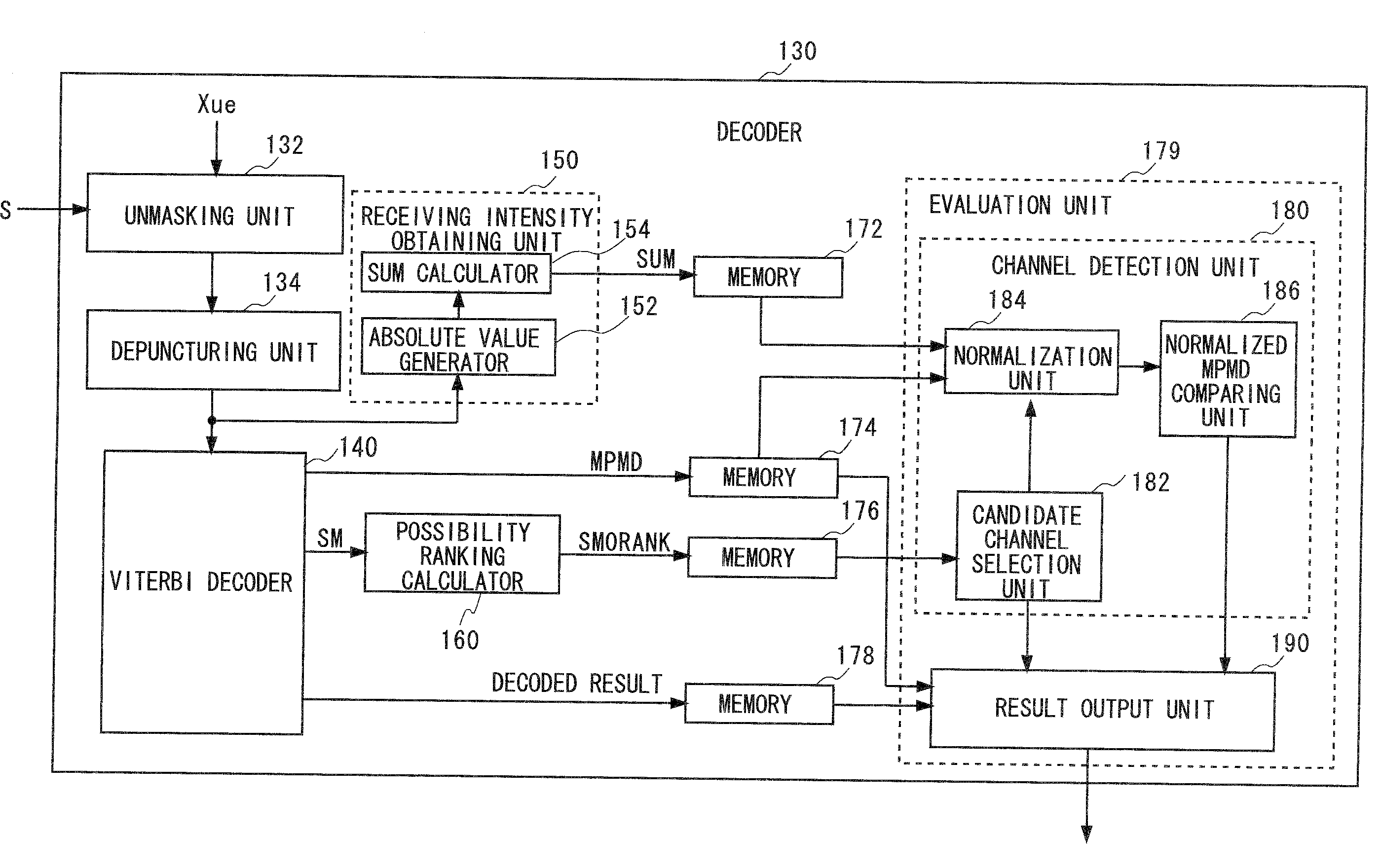
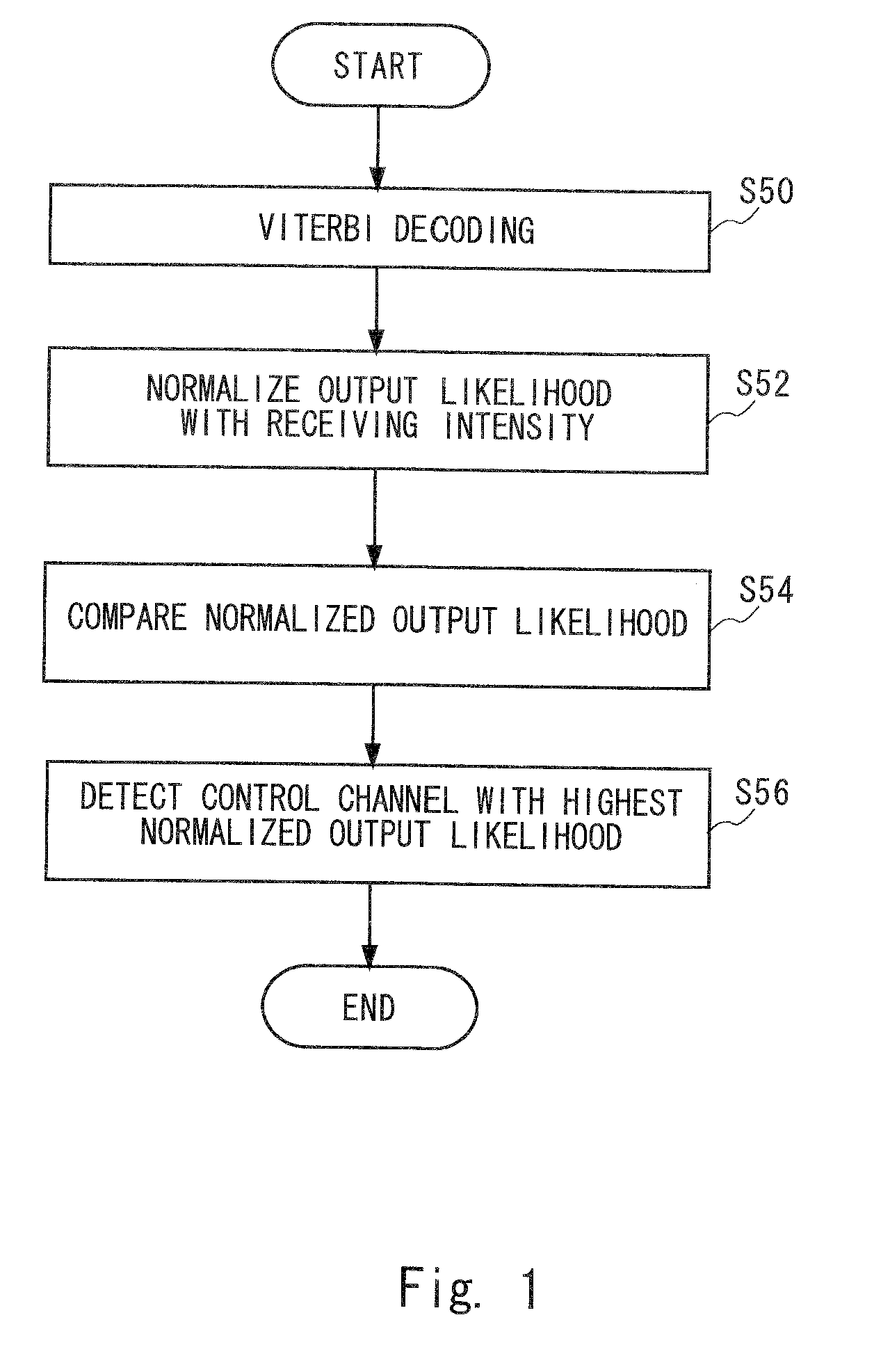
[0058]FIG. 1 is a flowchart showing the first method established by the inventors. First, Viterbi decoding is performed to each data of a plurality of received control channels (S50). An output likelihood is obtained for each control channel by the Viterbi decoding. Any one or combination of the following likelihood can be used as the output likelihood in each state existing at a respective point in the trellis diagram; a likelihood indicated by a minimum path metric difference MPMD, a ...


PUM


Abstract

For each of a plurality of control channels, a likelihood indicated by a state metric of each state at the last point which is obtained at the time of Viterbi decoding is obtained. This Viterbi decoding is not cut off and performed to convolutionally coded data of the corresponding control channel. The ranking of the likelihood is obtained as a possibility ranking SM0RANK indicating the possibility of the control channel to be a control channel for a particular receiving apparatus. From the plurality of control channels, the control channels with the possibility ranking SM0RANK more or equal to a predetermined threshold are selected as candidate channels. An output likelihood of each candidate channel which is obtained in the Viterbi decoding is normalized with a receiving intensity of the corresponding candidate channel to detect a candidate channel having the highest normalized output likelihood as the control channel for the receiving apparatus.

Description

FIELD OF THE INVENTION[0001]The present invention relates to a technique for detecting a control channel for a particular receiving apparatus from a plurality of control channels received.DESCRIPTION OF RELATED ART[0002]In the field of wireless communications, the following communication method is used: a base station transmits control channel and data channel data and then a user equipment obtains control information from the control channel data to receive and decode data channel data according to the control information.[0003]For example, HSDPA (High Speed Downlink Packet Access) based on the specification of 3GPP (3rd Generation Partnership Project) defines HS-SCCH (High Speed-Shared Control Channel) and HS-PDSCH (High Speed Physical Downlink Shared Channel) as a control channel and a data channel. The information concerning HS-PDSCH is stored in HS-SCCH. A user equipment obtains these information from HS-SCCH to receive and decode HS-PDSCH (see Japanese Unexamined Patent Applic...

Claims


Application Information

Patent Timeline
IPC IPC(8): H04L27/06
CPCH03M13/3738H03M13/41H03M13/653H04L1/0068H04L1/0054H04L1/0065H03M13/658
Inventor SHIMIZU, MASAKAZU
Owner RENESAS ELECTRONICS CORP
Why Eureka
Try Eureka