Development Roller, Development Device, and Image Forming Apparatus

Inactive Publication Date: 2009-08-20
SEIKO EPSON CORP
View PDF26 Cites 6 Cited by
  • Summary
  • Abstract
  • Description
  • Claims
  • Application Information

AI Technical Summary

Benefits of technology

[0023]Uneven sliding of the toner regulator blade on the development roller and a sound of the toner regulator blade are effectively controlled. The breaking of the toner regulator blade may also be avoided. The durability of the development roller and the toner regulator blade are increased. The charging property of the development roller is maintained at an excellent level for a long period of time.
[0024]Since an increase in the contact level between the toner regulator blade and the flat portion of the projection is controlled, an increase in the drive torque of the development roller is also restricted for a long period of time.
[0025]The development device including the development roller can thus develop toner images on the

Problems solved by technology

Even if the durability of the development roller a is increased with the surface layer g, the level of durability of the development roller a is not sufficient.
The durability of the development roller a

Method used


Image

  • Development Roller, Development Device, and Image Forming Apparatus
  • Development Roller, Development Device, and Image Forming Apparatus
  • Development Roller, Development Device, and Image Forming Apparatus

Examples


first embodiment

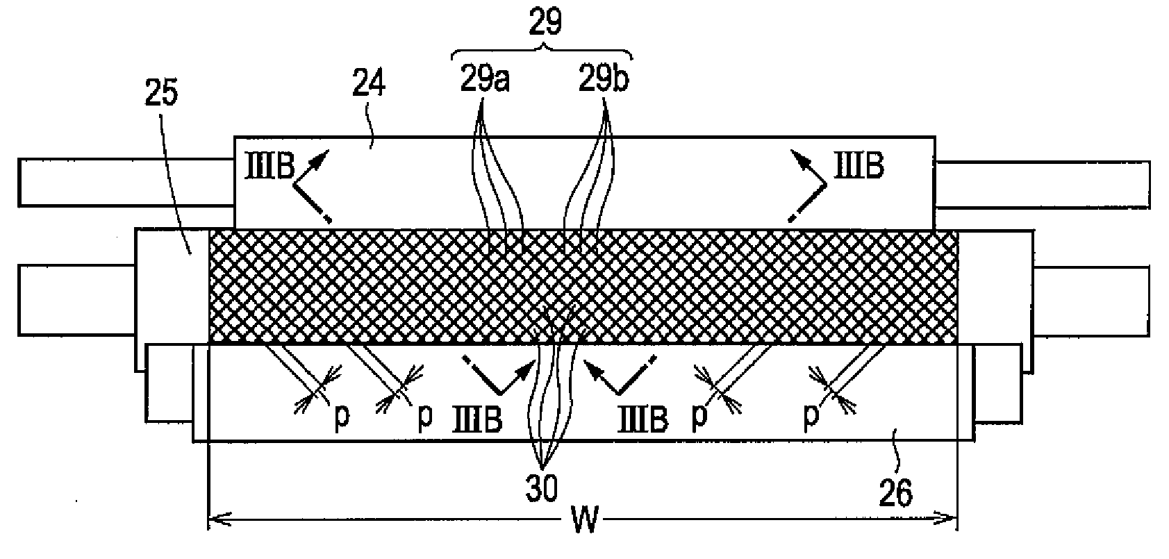
[0064]Swollen portions 30b′ of a predetermined number raised from a base flat surface 30a′ of the base projection 30′ (regular surface of the base unit 25a, i.e., the circumference surface of the base unit 25a) are formed at the upper side edge of the base projection 301 of the base unit 25a manufactured through component rolling as previously discussed with reference to FIG. 4A. Base recesses 30c′ of a predetermined number dented downward from the base flat surface 30a′ may be formed within the upper side edges of the base flat surface 30a′ of the base projection 30′. The height of the swollen portions 30b′ from the base flat surface 30a′ and the depth of the base recesses 30c′ are respectively negligibly smaller than the height of the base projection 301 and the depth of the first and second base grooves 29a′ and 29b′. The swollen portion 30b′ of the base projection 30′ causes a swollen portion 30b raised from the flat surface 30a to be formed at the upper side edge of the project...

second embodiment

[0095]Referring to FIG. 9A, a plurality of small recesses 30c′ dented downward from the base flat surface 30a′ (only one base dent 30c′ is illustrated in FIG. 9A) are formed in the base flat surface 30a′ of the base projection 30, of the base unit 25a as previously discussed. These base recesses 30c′ are created by making streak scratches with any appropriate means in a surface finish process prior to the roughening process of the base unit 25a. Instead of streak base recesses 30c′, the base recesses 30c′ may be formed using micro blasting.

[0096]The base flat surface 30a′ of the base projection 30′ with a plurality of micro base recesses 30c′ has a predetermined surface roughness r′. The surface layer 25b of the flat surface 30a at the projection 30 covering the base flat surface 30a′ of the base projection 30′ also has a plurality micro recesses 30c dented downward from the flat surface 30a in accordance with the base recesses 30c′. In such a case, the surface layer 25b is produced...


PUM


Abstract

A development roller includes a base unit having a base recess and a base projection that are formed in a predetermined area of a circumference surface of the base unit by pressing a regular pattern in pressure machining, and a surface layer formed on the circumference surface of the base unit and having a recess and a projection formed respectively in accordance with the base recess and the base projection of the base unit. A thickness of the surface layer is larger than a maximum height of a base swollen portion close to the side edge of the base projection from a regular surface of the base projection.

Description

BACKGROUND[0001]1. Technical Field[0002]The present invention relates to a development roller having a roughness on the circumference thereof for transporting toner to a latent image bearing unit, a development device containing the development roller, and an image forming apparatus containing the development device.[0003]2. Related Art[0004]Development devices developing a toner image from a latent image with one-component non-magnetic toner triboelectrically charge the toner on a development roller. The development roller has a surface roughness on the circumference thereof, the roughness having a substantially flat top surface. The development roller includes a base unit having a roughness portion of grooves on the circumference thereof formed through component rolling, and a surface layer having a uniform thickness formed through plating on the surface of the base unit (as disclosed in Japanese Unexamined Patent Application Publication No. JP-A-2007-121948).[0005]As illustrated ...

Claims


Application Information

Patent Timeline
IPC IPC(8): G03G15/08
CPCG03G15/0818
Inventor YAMADA, YOICHIMAEDA, MASAHIROSUZUKI, JUNICHIFUKUMOTO, TAKATOMO
Owner SEIKO EPSON CORP
Why Eureka
Try Eureka