
Remotely Operated Underwater Vehicle

a remote-operated, underwater technology, applied in underwater equipment, special-purpose vessels, television systems, etc., can solve the problems of reducing efficiency even further, affecting the safety of underwater vehicles, and not optimally optimizing the configuration.

Inactive Publication Date: 2009-08-20
HAWKES CALVERT T
View PDF7 Cites 6 Cited by
  • Summary
  • Abstract
  • Description
  • Claims
  • Application Information

AI Technical Summary

Benefits of technology

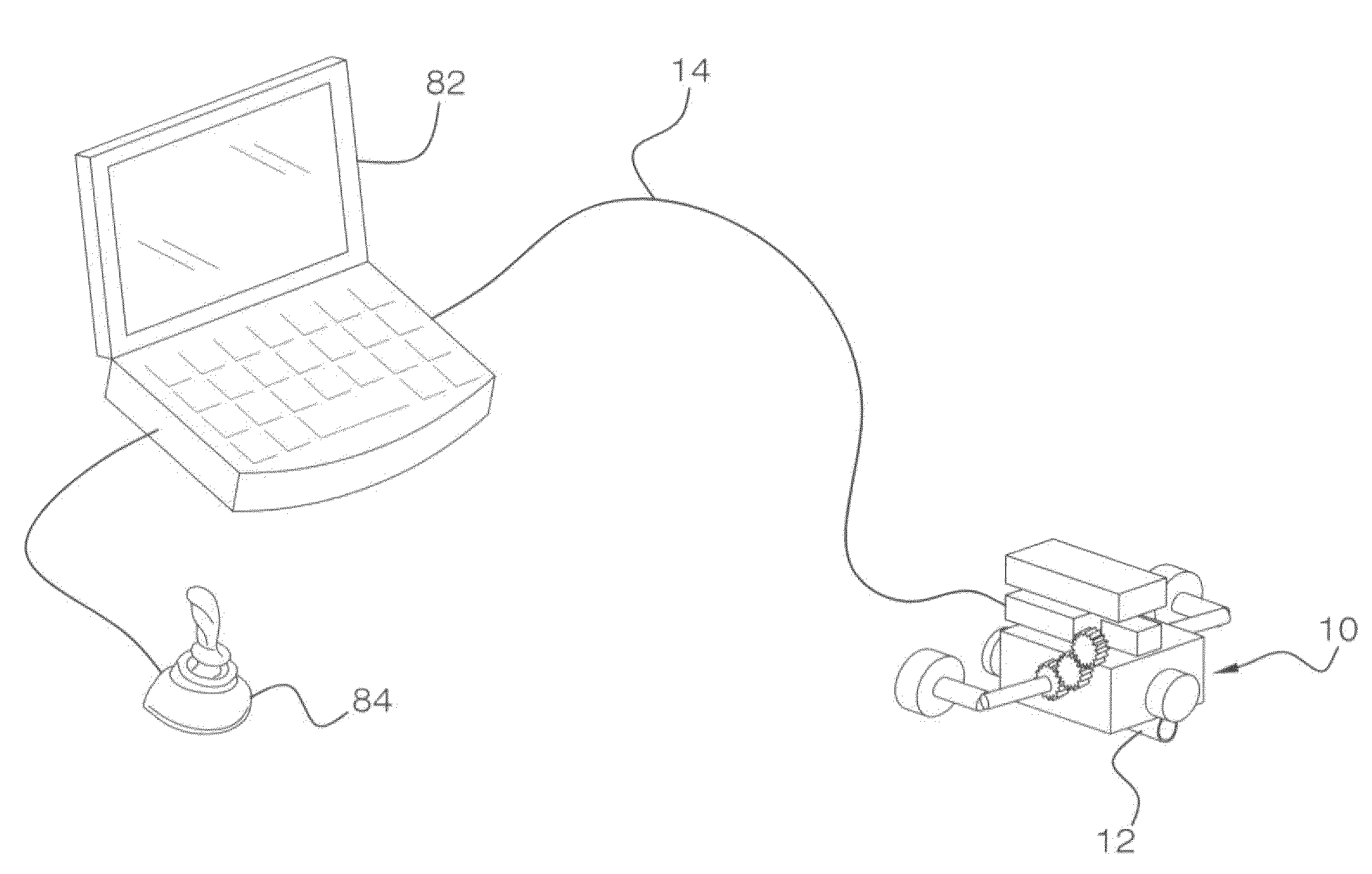
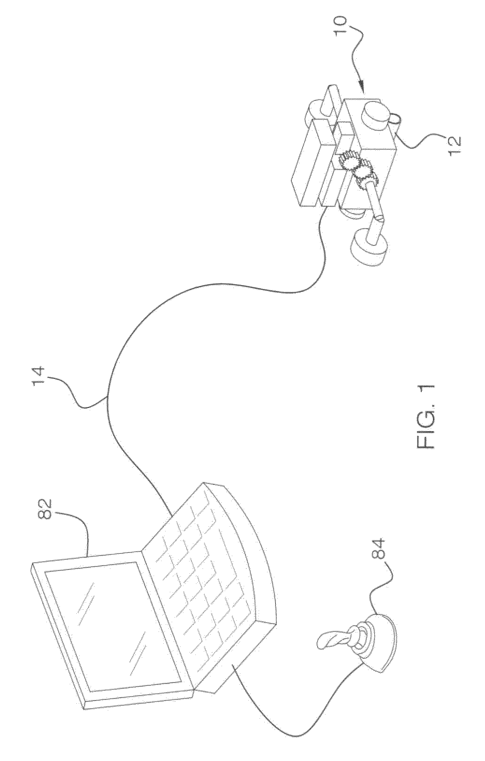
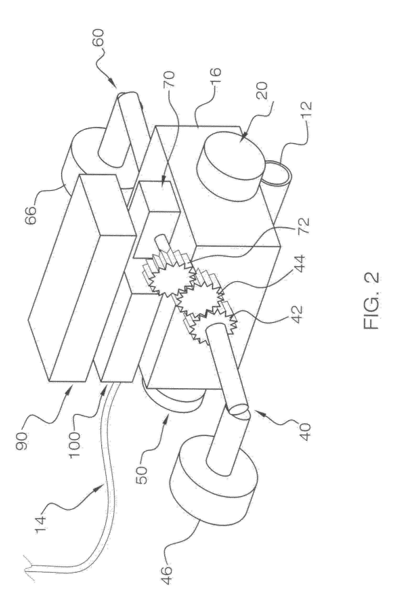
[0013]This invention uses two horizontally opposed propellers, which can be rotated into the horizontal or vertical planes, to drive the ROV. The control electronics includes an electrically isolatable programming port that allows the electronics to be reprogrammed. All signal including video are run through standard category 5 network cable (Cat5 cable), reducing weight and cost.
[0015]To move the ROV up and down, the servo rotates the propellers to the vertical orientation. The direction of the propellers then controls whether the ROV moves up or down, and the relative speed of the propellers controls the roll of the ROV. In addition, the servo motor can position the propellers in between the horizontal and vertical planes, to provide a motion that combines both horizontal and vertical components. When operating in this manner, the floatation at the top of the ROV provides stability and reduces any tendency for unwanted roll.

Problems solved by technology

Since motors are generally heavy, this configuration is not optimally efficient.
The situation is typically worse when moving vertically because the multiple horizontal thrusters that are idle reduce the efficiency even further.
Another problem with ROVs relates to the electronics.
This allows for access to perform reprogramming of the electronics, but causes a problem because opening and resealing the watertight enclosure may be time consuming.
A solution to this problem may be to run the reprogramming signals through the tether, but this has the disadvantage of adding to the size, weight and cost of the tether.
This solution has not typically been employed in past ROVs because once encapsulated, either the electronics cannot be reprogrammed, or as mentioned above the reprogramming wires must be run through the tether.
Another problem with existing ROVs is that in general an expensive tether is required.
A standard solution is to use a custom cable for the tether, but this adds to the cost of the ROV.
The problem with this method is that the batteries add weight to the ROV and the modulation circuitry can be expensive.

Method used


Image

  • Remotely Operated Underwater Vehicle
  • Remotely Operated Underwater Vehicle
  • Remotely Operated Underwater Vehicle

Examples


case 16

[0031]Case 16 provides the attachment points for camera 12, drive motors 20 and 50, drive arms 40 and 60, servo 70, floatation 90 and control electronics 100. Floatation 90 counterbalances the weight of the ROV to provide approximately neutral buoyancy. For shallow operation, a block of closed cell foam can be used. For deeper operation, the foam can be covered in a solid outer shell such as fiberglass, or a sealed container or other hard buoyant object can be used for floatation.

[0032]Right arm gear 42 is connected to right arm 40, and the corresponding left arm gear 62 is connected to left arm 60. Servo gear 72 is connected to servo 70, and drives right idler gear 44, which also connects to rotation shaft 74. Shaft 74 also connects to left idler gear 64, shown in left perspective view FIG. 3. When servo 70 turns servo gear 72, right idler gear 44 rotates right arm 40 and also rotates rotation shaft 74 and left idler gear 64, which rotates left arm 60. In this fashion servo 70 cont...


PUM


Abstract

A remotely operated underwater vehicle includes a case to which is attached a camera for transmitting video to a remotely located base station. A tether having four pairs of twisted wire operably connects the underwater vehicle, and the camera to the base station. Video is transmitted from the camera to the base station on a pair of twisted wire.

Description

CROSS-REFERENCE TO RELATED APPLICATIONS[0001]This application is a divisional of U.S. application Ser. No. 11 / 502,084, entitled “Propulsion and Steering Mechanism for an Underwater Vehicle”, filed Aug. 10, 2006, which claims priority to provisional patent application Ser. No. 60 / 710,552, filed Aug. 23, 2005, the entirety of both are incorporated herein by reference.FIELD OF THE INVENTION[0002]This invention is directed to a remotely operated underwater vehicle, and more particularly to a Remote Operated Vehicle (ROV) tether and the transmission of video signals and power on the tether.BACKGROUND OF THE INVENTION[0003]Inspection class Remote Operated Vehicles (ROVs) are typically used to position a video camera underwater. The ROV usually contains electronics that are connected to a base station by a wire tether. Motor driven propellers called thrusters are used to move the ROV.[0004]Current ROVs, for example as described in U.S. Pat. No. 6,662,742, generally use separate thrusters t...

Claims


Application Information

Patent Timeline
Patent Type & Authority Applications(United States)
IPC IPC(8): B63C11/48
CPCB63C11/42B63G8/08B63H25/42B63H23/02B63G8/16
Inventor HAWKES, CALVERT T.
Owner HAWKES CALVERT T
Learn More