Curing Light

a light and light technology, applied in the field of light therapy, can solve the problems of light outside of any light capture device wasted if allowed to escape, and achieve the effects of reducing power loss, reducing power loss, and reducing power loss

Inactive Publication Date: 2009-08-20
DEN MAT HLDG
View PDF55 Cites 42 Cited by
  • Summary
  • Abstract
  • Description
  • Claims
  • Application Information

AI Technical Summary

Benefits of technology

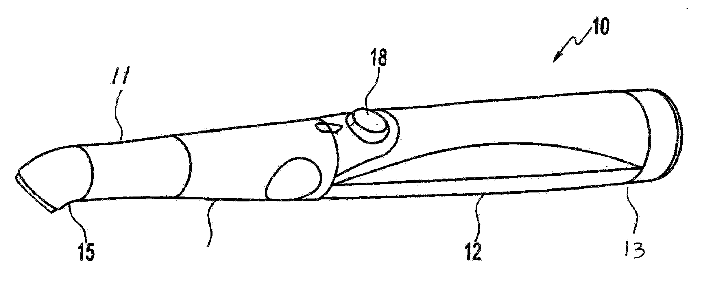
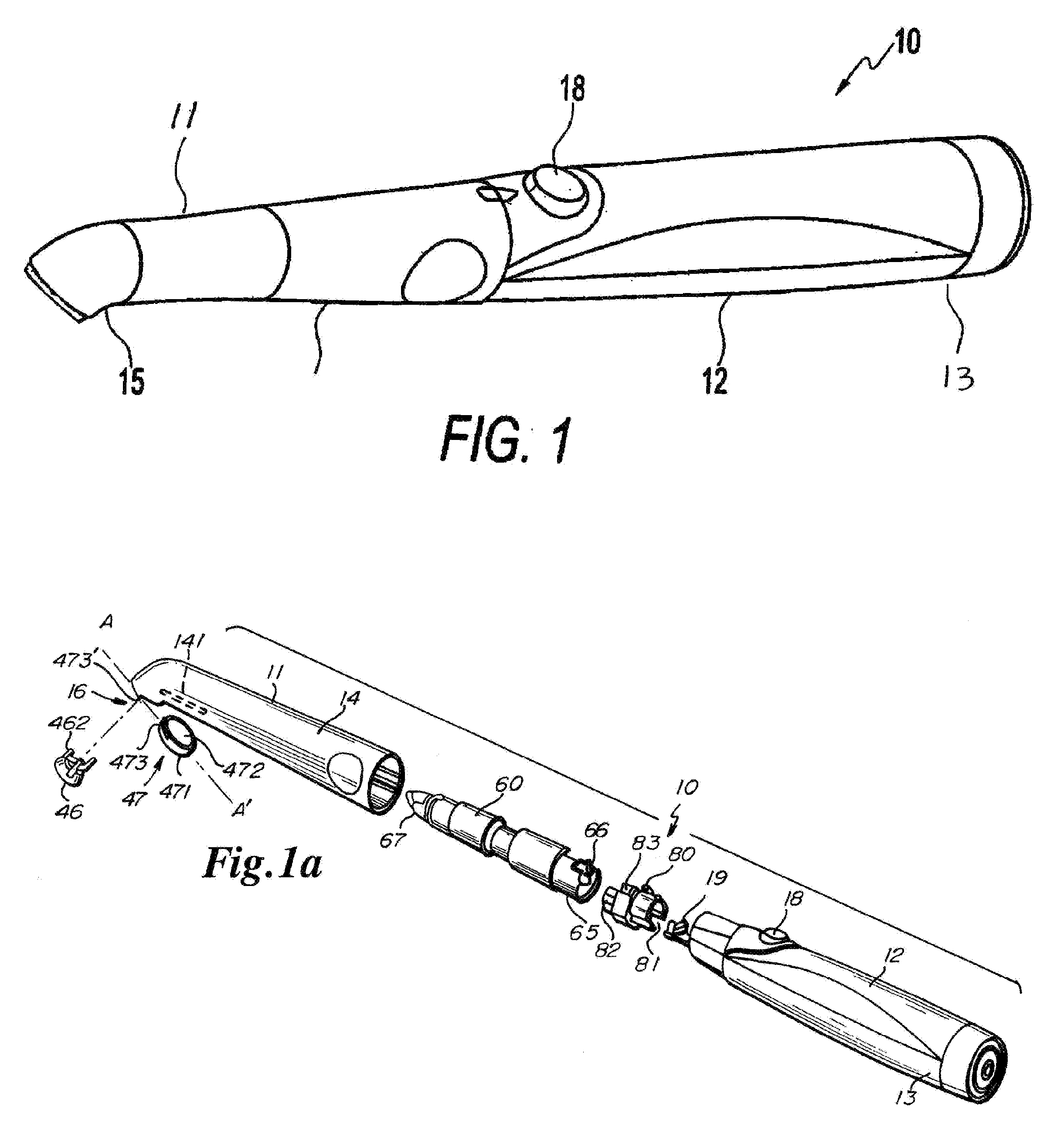
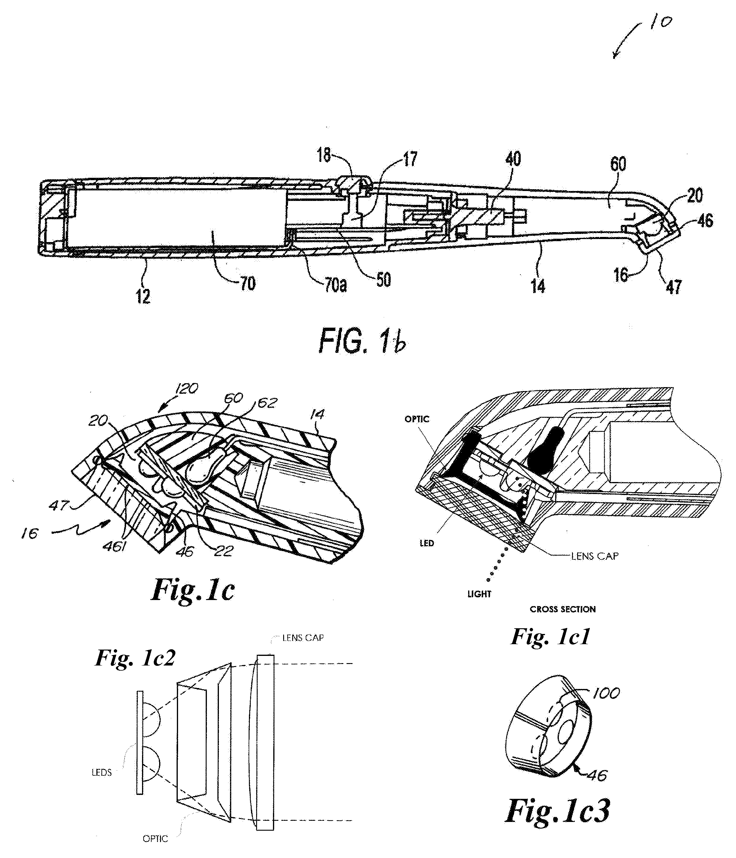
[0034]The present invention further relates to a dental curing light having a light source arrangement and an optical element combined to provide a larger effective beam diameter and surprisingly slower fall off in power as the distance between the emitting end of the curing light and the target for restoration increases. The light module housing includes a distal end and a proximal end, an elongated heat sink and at least one optical element formed on or attached to at least one light source, in any of the embodiments described above. The light module housing may have a substantially cylindrical shape defining a substantially hollow interior, a handle, a head and neck portion, which may be angled with respect to the rest of the housing. At least one mounting surface is located towards the proximal end of the elongated heat sink. The light source may be located at the distal end of the heat sink, and if a phase change heat sink is used, away from the capping device.
[0035]The curing light of the present invention is compact, light weight and portable.

Problems solved by technology

Most light sources emit light in a cone and any light outside of any light capturing device is wasted if allowed to escape.

Method used


Image

  • Curing Light
  • Curing Light
  • Curing Light

Examples


Embodiment Construction

[0084]The detailed description set forth below is intended as a description of the presently exemplary device provided in accordance with aspects of the present invention and is not intended to represent the only forms in which the present invention may be prepared or utilized. It is to be understood, rather, that the same or equivalent functions and components may be accomplished by different embodiments that are also intended to be encompassed within the spirit and scope of the invention.

[0085]Unless defined otherwise, all technical and scientific terms used herein have the same meaning as commonly understood to one of ordinary skill in the art to which this invention belongs. Although any methods, devices and materials similar or equivalent to those described herein can be used in the practice or testing of the invention, the exemplary methods, devices and materials are now described.

[0086]All publications mentioned herein are incorporated herein by reference for the purpose of d...


PUM


Abstract

The present invention relates to curing light devices for use in dentistry. Specifically, this invention relates to curing light devices generating convergent and uniform light with high intensity. The curing light device has a handle portion and a front portion wherein a light module is located in a desirable position in the interior of the front portion. The light module may include a light source comprising at least three LEDs in a compact manner, an optical element adapted to direct and/or focus the LEDs, and a lens cap to protect the LEDs and the optical elements. The lens cap may include a peripheral groove extending more than half of the periphery of the lens cap, which provides a longer engagement portion and thus a more secured attachment when “over-centeredly” engaging with a receiving edge on the light emitting end. A substantially precise alignment is achieved between the LEDs and corresponding lenses on the optical element to minimize heat dissipation and to increase the runtime and intensity of the curing light device. The curing light has an effective beam diameter of at least about 9 mm with output homogeneity of up to about 6 mm away from the emitting end.

Description

CROSS-REFERENCE TO RELATED APPLICATIONS[0001]This application claims the benefit of U.S. provisional patent application Ser. No. 61 / 029,558, filed Feb. 18, 2008, entitled “Curing Light”, the contents of which are hereby incorporated by reference.FIELD OF THE INVENTION[0002]This invention relates to a curing light device for use in dentistry. Specifically, this invention relates to a portable curing light device for dental curing purposes.BACKGROUND OF THE INVENTION[0003]In the field of dentistry, tooth restoration and repaired, dental cavities are often filled and / or sealed with compounds that are photosensitive, either to visible and / or ultraviolet light. These compounds, commonly known as light-curable compounds, are placed within dental cavity preparations or onto dental surfaces and are cured when exposed to light from a dental curing light device.[0004]Composite resin fillings have become the standard for filling cavities in dentistry today. These composites fillings use resins...

Claims


Application Information

Patent Timeline
Patent Type & Authority Applications(United States)
IPC IPC(8): A61N5/06
CPCA61C19/004A61N2005/0652A61N2005/0644A61N2005/0606
Inventor ORLOFF, MARCMURTAGH, JOHNPHAM, TRAVIS
Owner DEN MAT HLDG
Why Eureka
Try Eureka