

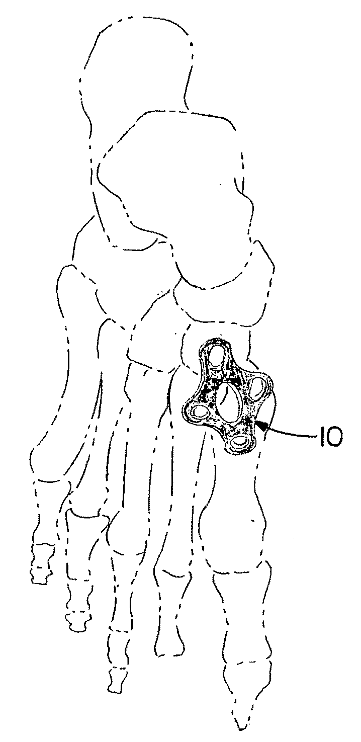
Orthopedic plate for use in the midfoot
a technology for orthopedic plates and midfoot, applied in the field of orthopedic plates, can solve the problems of severe fractures and/or dislocations, development of problems, and trauma to the midfoot, and achieve the effect of facilitating plate placemen
- Summary
- Abstract
- Description
- Claims
- Application Information
AI Technical Summary
Benefits of technology
Problems solved by technology
Method used
Image

Examples
second embodiment
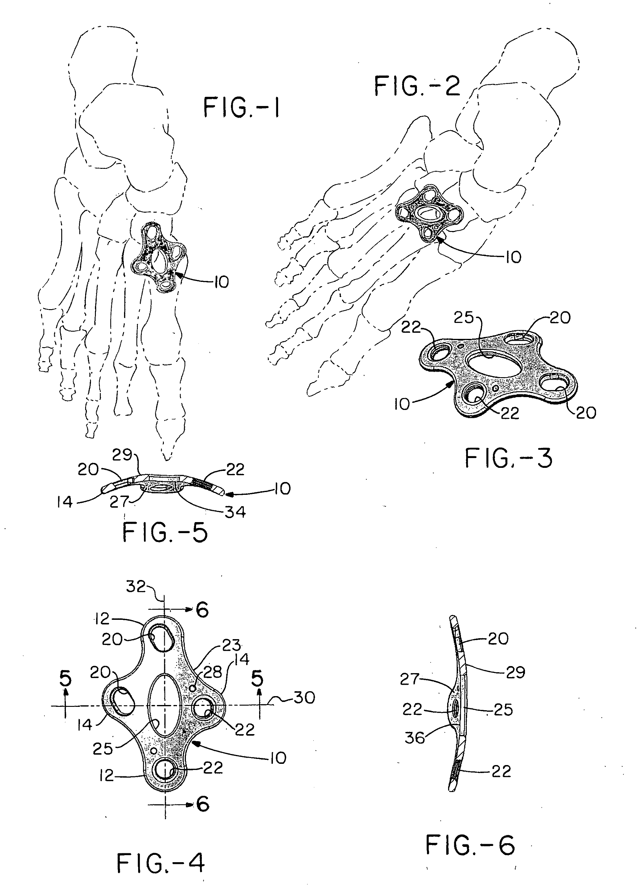
[0028]FIGS. 4 and 5 illustrate the plate in cross-section along a first axis and a perpendicular axis. As can be seen the plate has a generally uniform thickness between the inward surface 27 which opposes and optimally, but not necessarily engages the bones, and the outward surface 29. In addition, while the inward surface 27 of the plate 10 includes a generally uniform radius of curvature 34, 36 along both the first 30 and the second axis 32, the radii of these two curves differ (specifically the radius of the first curvature 34 is from about 50 to about 90, more preferably about 60 to about 80, and most preferably about 65 to about 75 millimeters, while the radius of the second curvature 35 is from about 10 to about 50, more preferably about 20 to about 40, and most preferably about 25 to about 35 millimeters. The first radius is from about 1 to about 4 times that of the second radius, and more preferably about 1.5 to about 3 times that of the second. Thus, the plate has the shap...
first embodiment
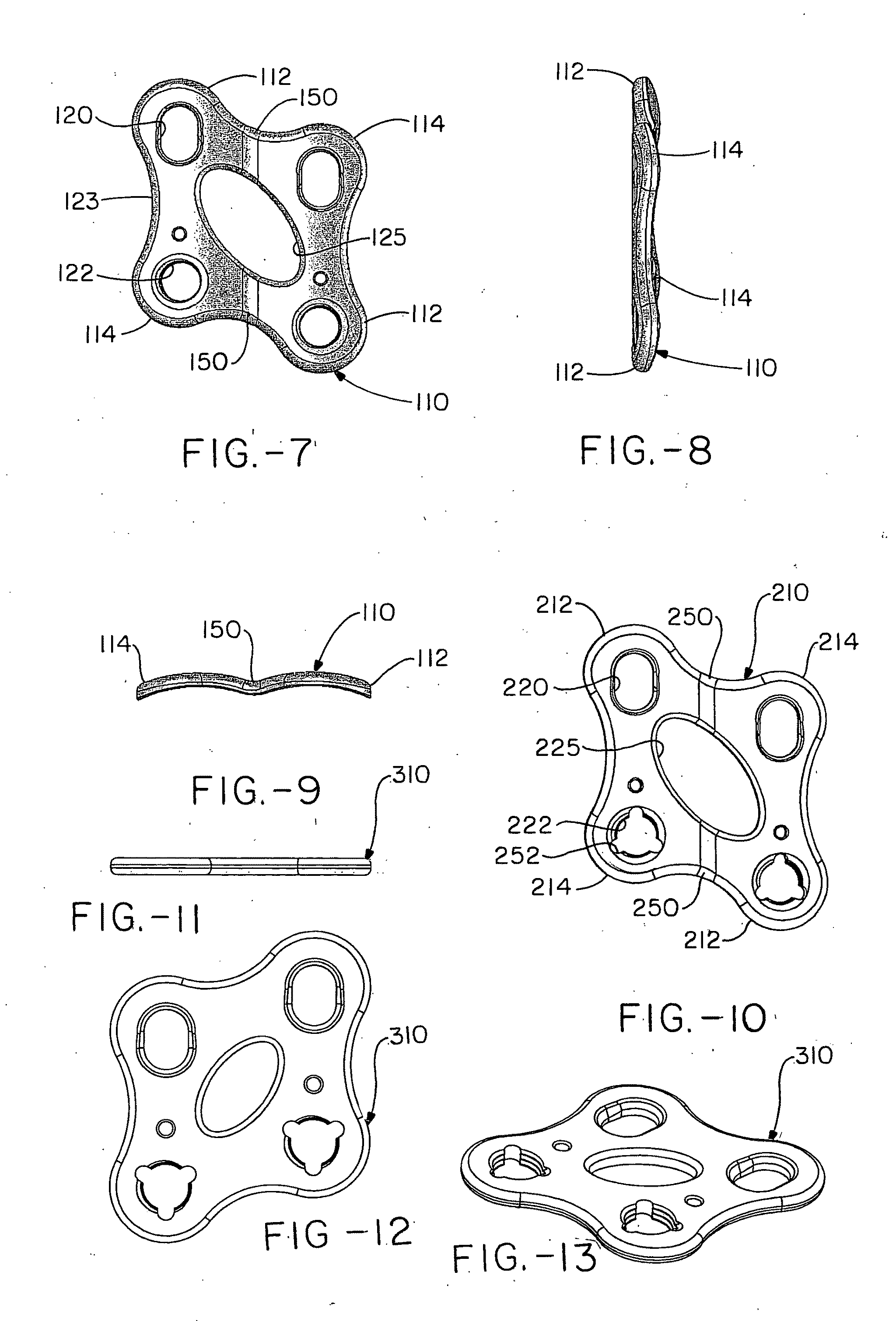
[0033]Further embodiments of the plate 110 (210) are shown in FIGS. 7-9, and 10 (which is the same as in FIGS. 7-9 but includes guide keyways). These embodiments include a similar peripheral shape as the first embodiment, with two sets of opposing diagonal tabs that are slightly offset from each other so as to define a kind of ring having a first set of diagonally opposed longer tabs 112 (212) and a second set of diagonally opposed shorter tabs 114 (214). Again, each of the set of longer and shorter tabs include a compression slot 120 (220), and the other of the pair of tabs includes a screw hole 122 (222) (which can include internal threads so as to form a locking interface with the respective bone or bone fragment.) The plate includes incurvatures 123 between the tabs to minimize the material used and maximize the fit. At the intersection of the tabs, the plate includes an opening 125 (225) which can be used to view the placement of the plate relative to the bones as well as for a...
PUM
 Abstract
Description
Claims
Application Information