
Firefighter pocket tool

a pocket tool and firefighter technology, applied in the field of multi-use tools, can solve the problems of not providing a plier-type arrangement, no known prior art combination tool is designed to be especially suited to the needs of firefighters, and no known prior art provides a wide-opening spanner wrench. achieve the effect of reducing the bulk and combined weight of carrying

Inactive Publication Date: 2009-08-27
LIONEL MIKE
View PDF8 Cites 7 Cited by
  • Summary
  • Abstract
  • Description
  • Claims
  • Application Information

AI Technical Summary

Benefits of technology

[0007]The objective of the firefighter pocket tool is to reduce the bulk and combined weight of carrying several tools, as well as making several tool functions available in one tool.
[0043]4) You can open the pliers' jaws to get more leverage.

Problems solved by technology

Unfortunately, none of the known prior art combination tools is designed to be especially suited to the needs of firefighters.
There is no disclosure of a wide opening spanner wrench that would be suitable for tightening or loosening standard diameter (i.e., 1½″, 2½″ and 3″) water hose couplings used by fire departments.
Moreover, none of the known prior art provides a plier-type arrangement which also provides the feature of a dedicated striking surface which may be of particular value to firemen who, in the course of an emergency, may need to carefully, without injuring themselves or others, gain access through a home or vehicle's window.

Method used


Image

  • Firefighter pocket tool
  • Firefighter pocket tool
  • Firefighter pocket tool

Examples


Embodiment Construction

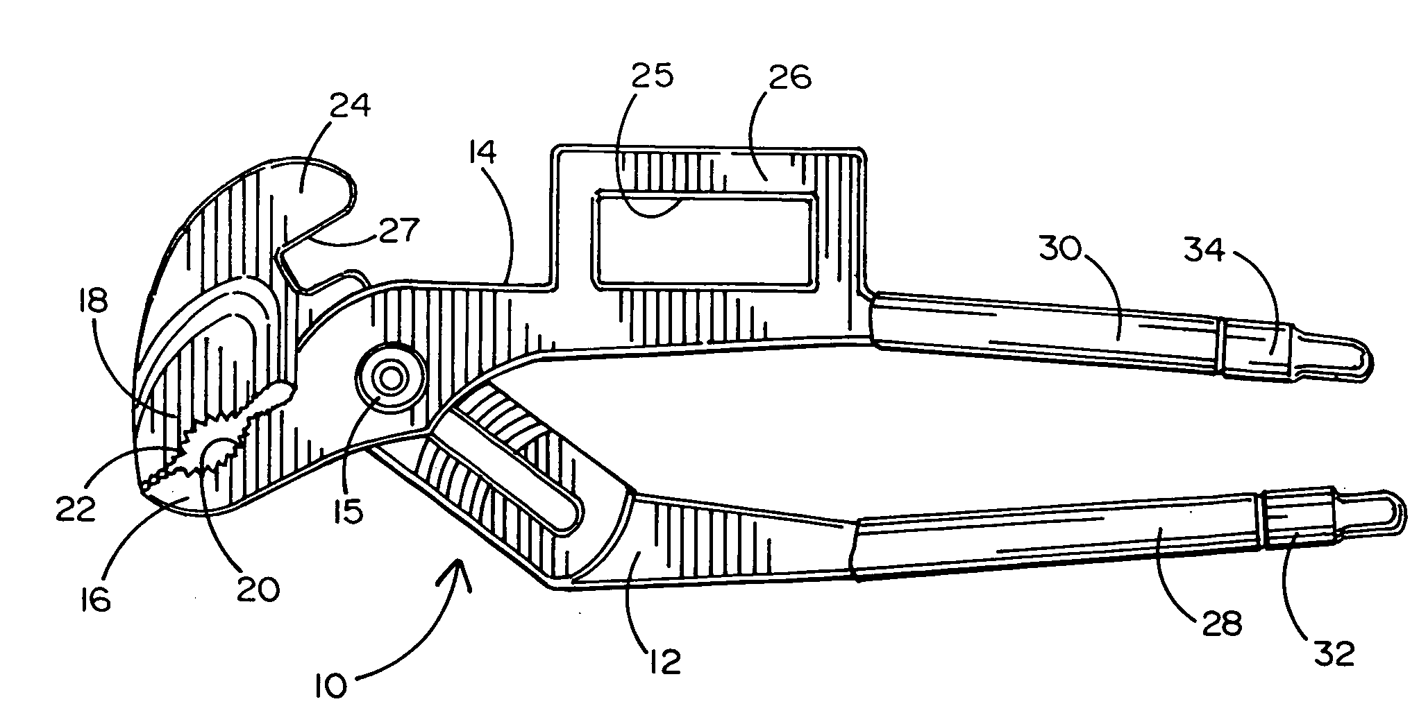
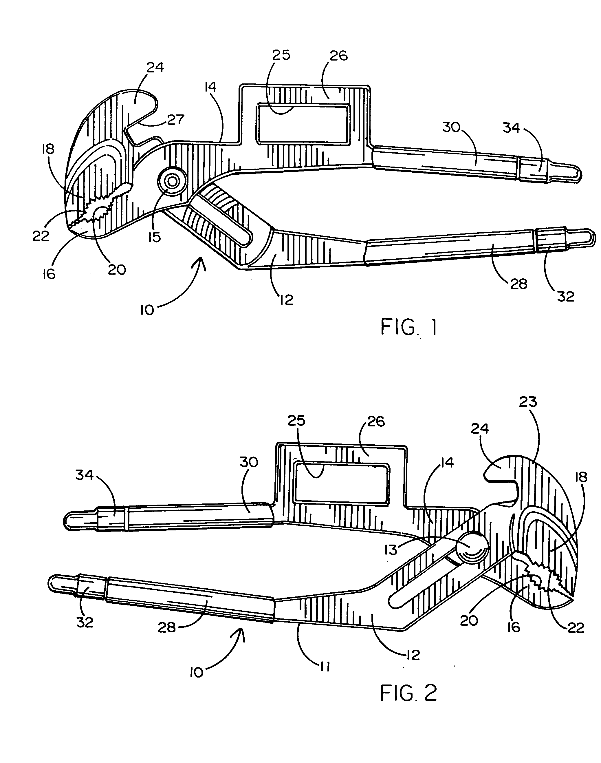
[0054]Referring now to the accompanying drawings and particularly to FIGS. 1 and 2, it will be seen that a firefighter's pocket tool 10 comprises a tongue-in-groove type plier 11 having mating members 12 and 14 held together for relative limited pivotal motion by a bolt 13 and nut 15. Members 12 and 14 terminate at one end respectively in mating jaws 16 and 18 which when closed form arcuate, serrated and substantially opposed gripping surfaces 20 and 22. Member 12 also comprises a striking surface 23 which terminates in a hook shaped extension 24 forming an arcuate recess 27. Members 12 and 14 terminate at a second end respectively in grasping handles 28 and 30.

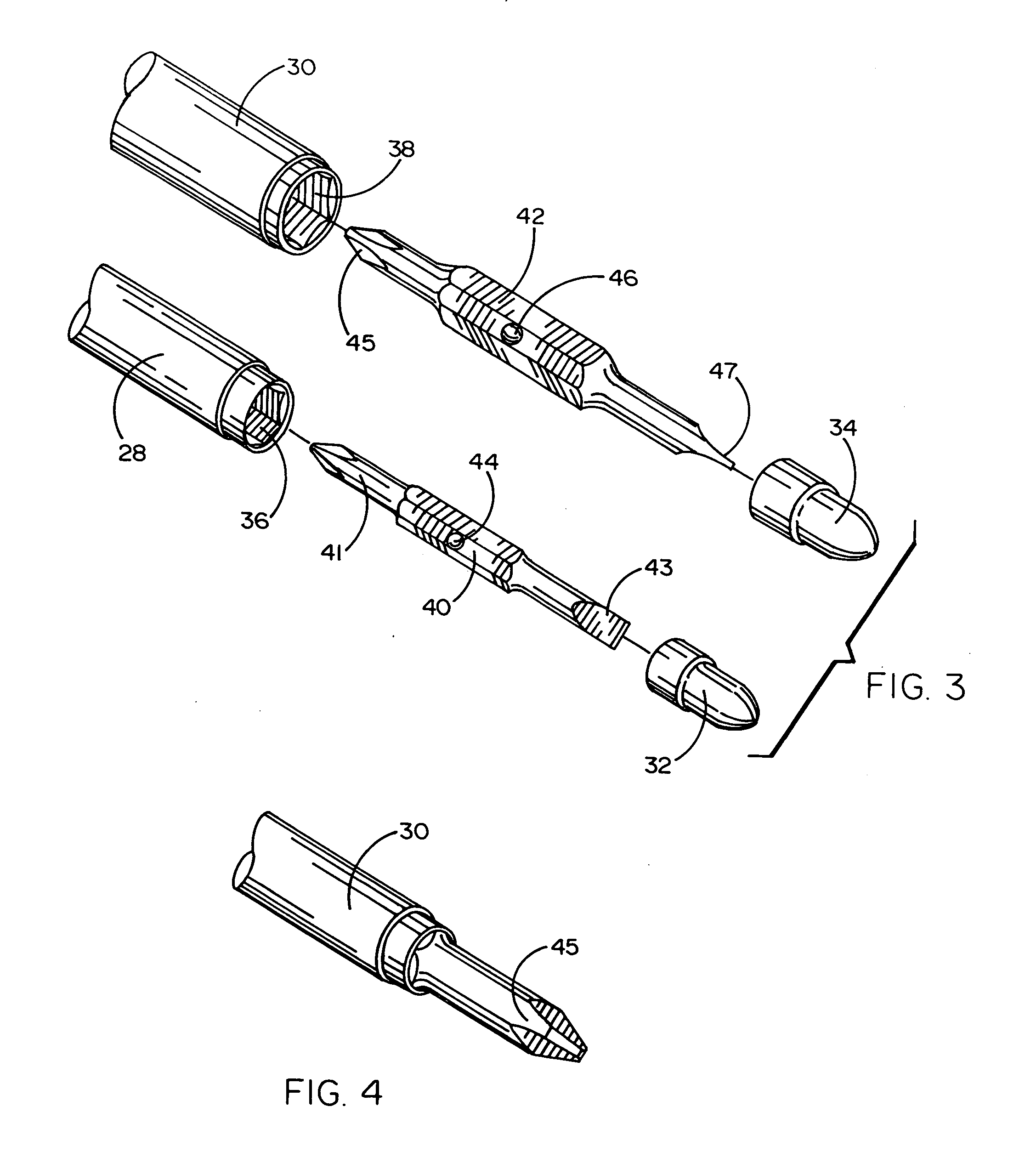
[0055]As seen best in FIGS. 3 and 4, handles 28 and 30 end with respectively open receptacles 36 and 38. These receptacles are of different diameters and have hexagonal cross-sections to retain respective screwdriver bits 40 and 42. Each such bit has opposed ends formed into phillips and flat head-type screwdrivers, respectiv...


PUM


Abstract

A firefighter pocket tool achieves its objectives by combining the functional features of several traditional tools (slip groove pliers of the curved jaw type, 6 in 1 screwdriver, spanner wrench, gas shut off tool and a striking tool) onto a shared single structure. The structure of the firefighter pocket tool comprises a pair of slip groove plier members each having a jaw portion, a joint portion and a handle portion, a pivotal bolt, nut and spring member. The upper jaw of the slip groove pliers is of the curved jaw type. Upon the “upper” rear portion of the pliers' “upper” jaw's head there is formed a protrusion that forms a striking surface and a hook and claw. The hook and claw is located so as to allow it to be used as a spanner for rocker lug type and similar fire hose couplings. As this same plier member crosses over the other plier member, it forms a plurality of arcuate adjustable channels with which the arcuate protuberance from the other plier member is engaged. Protruding from the top or rear handle (just above the gripping area) is another protrusion. This protrusion is of a rectangular shape. In the middle of this protrusion is a loop in the shape slightly larger than standard natural gas shut off valves. Two independently sized hexagonal open shafts that form the handles and nut-driver / bit holders. The spanner hook and claw could also be used to operate valves (such as smaller gas supply shut offs). The gas shut off loop can also be used as a guard for fingers when the tool is being used as a striking implement.

Description

BACKGROUND OF THE INVENTION[0001]1. Field of the Invention[0002]The present invention relates generally to the field of multi-use tools. The invention relates more specifically to the field of firefighter pocket tools.[0003]2. Background Art[0004]The relevant prior art includes numerous issued U.S. patents which disclose unique tools configured to combine different tool functions into a unitary structure. By way of example, U.S. Pat. No. 4,920,593 to Finn also shows a tongue-in-groove type pliers with handles which terminate in screwdriver-shaped features. Another such combination tool is disclosed in U.S. Pat. No. 4,995,128 to Montgomery et al which shows pliers having handles which provide a crescent wrench and a screwdriver bit receptacle. Other such combination tools are shown in U.S. Pat. Nos. 5,014,379; 5,251,353 and 5,327,602.[0005]Unfortunately, none of the known prior art combination tools is designed to be especially suited to the needs of firefighters. Thus for example, t...

Claims


Application Information

Patent Timeline
Patent Type & Authority Applications(United States)
IPC IPC(8): B25F1/00B25B7/02B25F1/02B25B7/22
CPCB25F1/02B25B7/22
Inventor LIONEL, MICHAEL ALAN PHILIP
Owner LIONEL MIKE
Learn More