Intra-oral dental-image sensor system with multiple leds

a dental image sensor and intraoral technology, applied in the field of dental radiological systems using intraoral image sensors, can solve the problems of inconvenient patient care, bulky overall installation, and risk of being pulled out, and achieve the effect of reducing the bulk and weight of the intraoral sensor and further enhancing the omnidirectional character of the emission

Inactive Publication Date: 2010-02-18
TELEDYNE E2V SEMICON SAS
View PDF2 Cites 6 Cited by
  • Summary
  • Abstract
  • Description
  • Claims
  • Application Information

AI Technical Summary

Benefits of technology

[0016]It will be understood that it would be possible to use five diodes, on substrates that are at 90° to each other, four substrates forming a square-based cylinder and the fifth closing this cylinder on one side. A number of light-emitting diodes greater than 5 is even conceivable to increase further the omnidirectional character of the emission.
[0017]Whatever the number of light-emitting diodes used, according to the invention it is preferred for the self-contained electrical power-supply of the intraoral sensor (primary cell or rechargeable battery) to be placed not inside but outside the mouth, the electrical cable being used to transmit power-supply energy from the source outside the mouth to the sensor inside the mouth. This makes it possible notably to reduce the bulk and the weight of the intraoral sensor, and that makes it possible to use a rechargeable battery rather than a primary cell. The advantage of a rechargeable battery over a primary cell is that a primary cell would often need to be changed. The rechargeable battery has the disadvantage of being more bulky, but the bulk is much less inconvenient once it is located outside the mouth. The electrical connection through the cable makes it possible to position the battery outside the mouth, the cable being used not only to transmit image information from the sensor array toward the light-emitting diodes, but also to transmit to the sensor array the energy necessary for its operation.

Problems solved by technology

The drawback of a cable connection is that it is fragile (risk of being pulled out), inconvenient for the patient if the cable is accidently pulled, and bulky in the overall installation.
In addition, in the medical environment the constraints of electrical insulation between the patient and the surrounding electrical power supplies are heightened and it is hardly in accordance with these constraints to connect a mains-powered device (microcomputer) to a module that is in the patient's mouth.
As wireless energy supply (typically by inductive transmission) is not very convenient, it is generally preferred to use a small-sized battery in the sensor placed in the mouth.
However, the difficulty arises in that this radio transmission may then be strongly interfered with through the presence of other radio transmitters which are being used increasingly in IT environments; WiFi or Bluetooth peripherals and computer cards may in particular strongly interfere with the transmission of image data from the sensor to the image user system.
This difficulty can be reduced by emitting the messages in a redundant manner in order to ensure complete and reliable transmission of every image, but this is time consuming when the information to be transmitted is already of a large quantity (typically several tens of megabits per image).
The complex electronics for reception, analysis and intelligent processing that results from this makes it very difficult to put the assembly into the patient's mouth.
The bulk and the power consumption are prohibitive.
Such an installation is complex.
However, the efficiency of the light transmission toward the receiver is not optimum.

Method used


Image

  • Intra-oral dental-image sensor system with multiple leds
  • Intra-oral dental-image sensor system with multiple leds
  • Intra-oral dental-image sensor system with multiple leds

Examples


Embodiment Construction

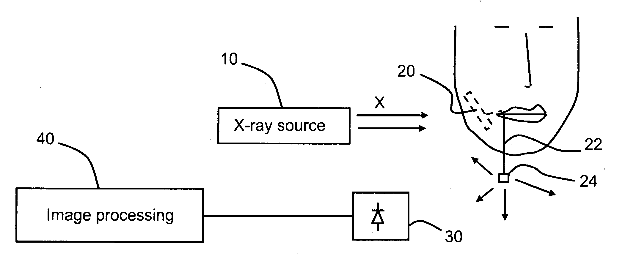
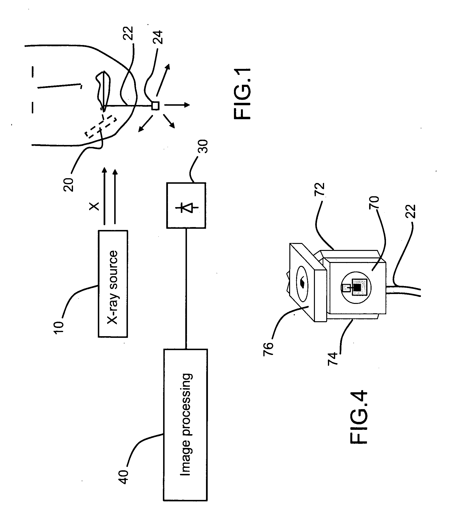
[0027]FIG. 1 shows the dental radiological system according to the invention in schematic form: it comprises an X-ray source 10 capable of emitting an X-ray flash toward the part of the jaw to be examined, a radiological image sensor 20 placed in the patient's mouth and shown in dotted lines, a photosensitive receiver 30 located outside the patient's mouth but not electrically connected to the sensor, and a system for using the signal received by the receiver. This user system 40 is designated in FIG. 1 as the image processing system, image processing being taken in the broad sense and possibly including, for example, receiving and demodulating digital light signals detected by the receiver, in order to extract from them image information which they are carrying and in order to transform the demodulated signals into an electronic image. This image is intended to be stored in a memory of the system or displayed on a display screen (not shown).

[0028]The core of the radiological image ...


PUM


Abstract

The invention relates to intraoral radiological dental image sensors, i.e. sensors placed in the mouth of a patient, an X-ray source being located outside the cheek of the patient in order to emit X-rays in the direction of the sensor. According to the invention, the image sensor is attached to a first end of a short electrical cable (22) of around 5 to 20 cm, a second end of which leaves the patient's mouth when the sensor is in the mouth, the second end carrying a light source (24) comprising light-emitting diodes that can be digitally modulated as a function of information coming from the sensor, the electrical cable being able to transmit an electrical control signal from the sensor to the diode for modulating the latter.

Description

CROSS-REFERENCE TO RELATED APPLICATIONS[0001]The present Application is based on International Application No. PCT / EP2007 / 061913, filed on Nov. 6, 2007, which in turn corresponds to French Application No. 0610079, filed on Nov. 17, 2006, and priority is hereby claimed under 35 USC §119 based on these applications. Each of these applications are hereby incorporated by reference in their entirety into the present application.FIELD OF THE INVENTION[0002]The invention relates to dental radiological systems using an intraoral image sensor, i.e. a sensor placed in the mouth of a patient, an X-ray source being located outside the cheek of the patient in order to emit X-rays in the direction of the sensor.BACKGROUND OF THE INVENTION[0003]Usually, in order to transmit the image information coming from the sensor placed inside the mouth to a receiver system, a cable connection that is also used to control the sensor and supply it with energy.[0004]The drawback of a cable connection is that it...

Claims


Application Information

Patent Timeline
Patent Type & Authority Applications(United States)
IPC IPC(8): A61B6/14
CPCA61B5/0017A61B5/4547G03B42/042A61B6/4233A61B6/563A61B6/145
Inventor AYRAUD, MICHEL
Owner TELEDYNE E2V SEMICON SAS
Why Eureka
Try Eureka