Feed arm for a multiple circuit fuel injector

a fuel injector and feed arm technology, which is applied in the field of fuel injectors, can solve the problems of ineffective or unusable fuel injectors, stagnant fuel may be present in the secondary fuel flow passage, and common coking of fuel within the secondary fuel flow passage, and achieve the effect of facilitating heat transfer

Active Publication Date: 2009-08-27
COLLINS ENGINE NOZZLES INC
View PDF6 Cites 39 Cited by
  • Summary
  • Abstract
  • Description
  • Claims
  • Application Information

AI Technical Summary

Problems solved by technology

When coking occurs, solid deposits can form within the fuel flow passage, which restricts the flow of fuel through the passage and can render the fuel injector ineffective or unusable.
As a result, stagnate fuel may be present in the secondary fuel flow passage.
Because the secondary fuel flow passage has a reduced fuel velocity, and because the secondary fuel flow passage is in close proximity to the extreme heat generated by the combustion chamber, coking of the fuel within the secondary fuel flow passage is a common problem.

Method used


Image

  • Feed arm for a multiple circuit fuel injector
  • Feed arm for a multiple circuit fuel injector
  • Feed arm for a multiple circuit fuel injector

Examples


Embodiment Construction

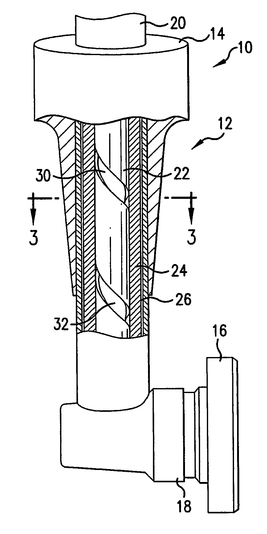
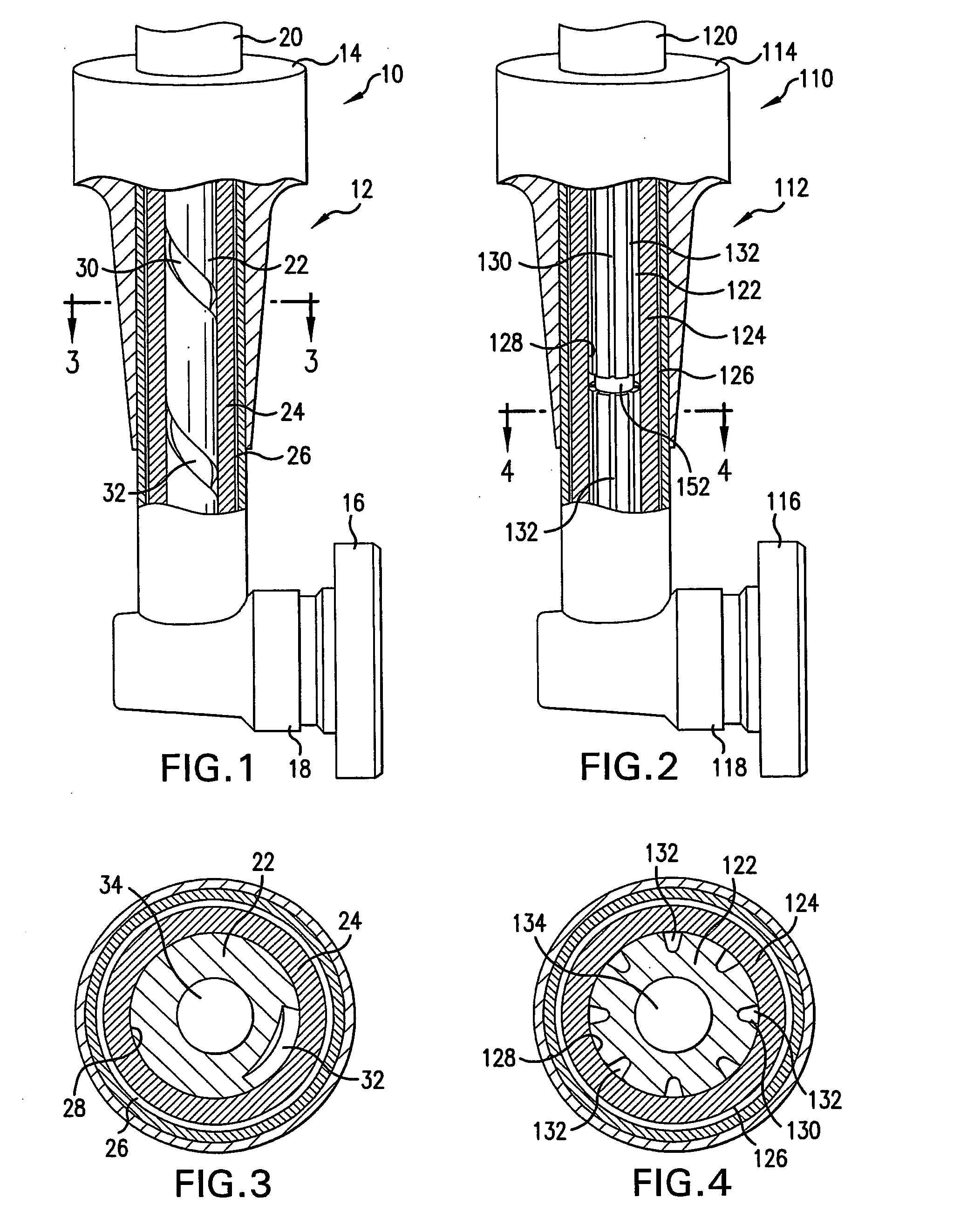
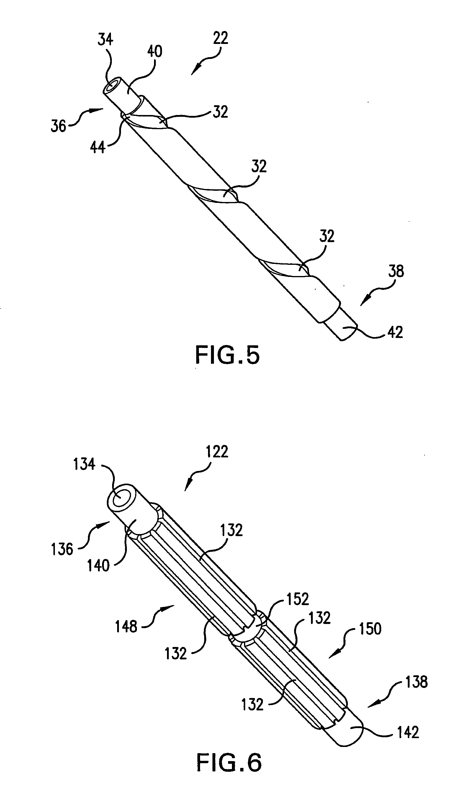
[0020]Referring now to the drawings, wherein like reference numerals identify or otherwise refer to similar structural features or elements of the various embodiments of the subject invention, there is illustrated in FIGS. 1, 3, and 5, an exemplary embodiment of a multiple circuit fuel injector designated generally by reference character 10. Other embodiments of the fuel injector are provided in FIGS. 2, 4, and 6, as will be described. Reference will now be made in detail to the present preferred embodiments of the invention, examples of which are illustrated in the accompanying drawings.

[0021]The subject invention is directed to a new and useful method of forming multiple fuel flow passages in a fuel injector, primarily for use in a gas turbine engine. A primary fuel passage of the subject invention is formed in the outer portion of a tubular structure and has a decreased cross-sectional area when compared to conventional fuel passages. This decreased cross-sectional area increases...


PUM

PropertyMeasurementUnit
inner diameteraaaaaaaaaa
outer diameteraaaaaaaaaa
axial lengthaaaaaaaaaa

Abstract

A feed arm for a multiple circuit fuel injector of a gas turbine engine. The feed arm includes an elongated tubular sleeve having a central bore with an interior wall defining an inner diameter, and an elongated fuel tube positioned within the bore of the tubular sleeve. The fuel tube includes a tubular wall defining an outer diameter, which is substantially equal to the inner diameter of the central bore. A primary fuel flow passage is formed within the tubular wall of the fuel tube and bounded by the interior wall of the tubular sleeve, and the primary fuel flow passage circumferentially extends around the fuel tube at least once along the axial length of the fuel tube. A secondary fuel flow passage extends through a central portion of the fuel tube, and the fuel tube is configured to facilitate heat transfer by conduction and / or convection.

Description

BACKGROUND OF THE INVENTION[0001]1. Field of the Invention[0002]The present invention relates to fuel injectors, and more particularly, to a feed arm for a multiple circuit fuel injector of a gas turbine engine.[0003]2. Description of Related Art[0004]Fuel injectors in gas turbine engines direct pressurized fuel from a manifold into one or more combustion chambers. Fuel injectors also function to prepare the fuel for mixing with air prior to combustion. Each injector typically includes an inlet near the manifold, one or more tubular fuel passages, and an outlet connected to a spray nozzle for introducing atomized fuel into a combustion chamber. The atomized fuel is then typically mixed with air and ignited, and the resulting expanded gas causes a plurality of turbine blades to rotate, thus providing power for propelling an aircraft or for other applications.[0005]Many fuel injectors include multiple fuel flow passages, allowing for the power output of the gas turbine engine to be mo...

Claims


Application Information

Patent Timeline
Patent Type & Authority Applications(United States)
IPC IPC(8): F02C7/228B23P13/00
CPCF02C7/222F23K5/20F23K2301/20Y10T29/494F23R3/343F23R3/36F23R3/28F23K2300/20F23D11/36F23R3/283
Inventor WILLIAMS, BRANDON P.
Owner COLLINS ENGINE NOZZLES INC
Why Eureka
Try Eureka