Apparatus And Method For Powering Load Center Circuits With An Auxiliary Power Source

a technology of load center circuit and power supply, which is applied in the direction of emergency power supply arrangement, relay, transportation and packaging, etc., can solve the problems of homeowner's inability to temporarily connect non-critical loads, load that exceeds the capacity of the generator, and operator's inability to opera

Inactive Publication Date: 2009-08-27
RELIANCE CONTROLS
View PDF2 Cites 47 Cited by
  • Summary
  • Abstract
  • Description
  • Claims
  • Application Information

AI Technical Summary

Benefits of technology

[0008]The present invention is directed to a combination of automatic and manual transfer switches either on separate buses in separate cabinets or on separate buses in the same cabinet. The automatic transfer switch allows the connection of critical circuits during a power outage. The critical circuits are selected such that the generator is not overloaded, as required by the National Electrical Code. The manual transfer switch allows for the connection of additional circuits to auxiliary power, which is allowed by the National Electrical Code. To safely accomplish combined use of an automatic transfer switch and a manual transfer switch, the present invention utilizes a series of interlocks and switches or circuit breakers that function to maintain manual and automatic separation of primary power and auxiliary power. In addition, the present invention prevents auxiliary power from being interpreted as primary power by the automatic system.
[0011]It is a further object of the invention to prevent control circuitry in an automatic transfer switch or auxiliary power supply from sensing the return of primary power when auxiliary power is available to the main panel.

Problems solved by technology

In this regard, during operation of the auxiliary power supply system, it is not possible for an operator, such as a homeowner, to power a non-critical load with the auxiliary power source in the event the homeowner happens to be home when the primary power source fails.
For instance, with conventional automatic transfer switches, a homeowner cannot temporarily connect a non-critical load, such as a television or radio, to the auxiliary generator when the primary power source fails.
However, in the system described by Hinks, it is possible for the normally closed manual feeder breaker and the normally open manual feedback breaker to both be closed at the same time, which can result in the entire load center being automatically connected to the auxiliary power source when the auxiliary power source is subsequently brought online, which not only is in violation of the U.S. National Electrical Code but also likely results in a load that exceeds the capacity of the generator.

Method used


Image

  • Apparatus And Method For Powering Load Center Circuits With An Auxiliary Power Source
  • Apparatus And Method For Powering Load Center Circuits With An Auxiliary Power Source
  • Apparatus And Method For Powering Load Center Circuits With An Auxiliary Power Source

Examples


Embodiment Construction

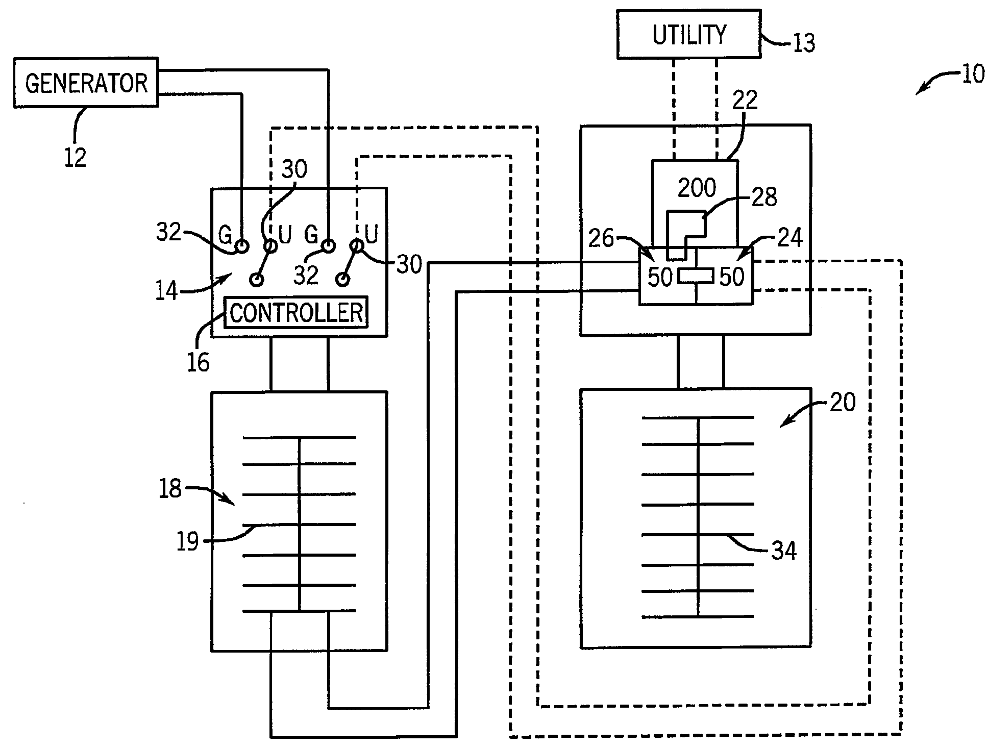
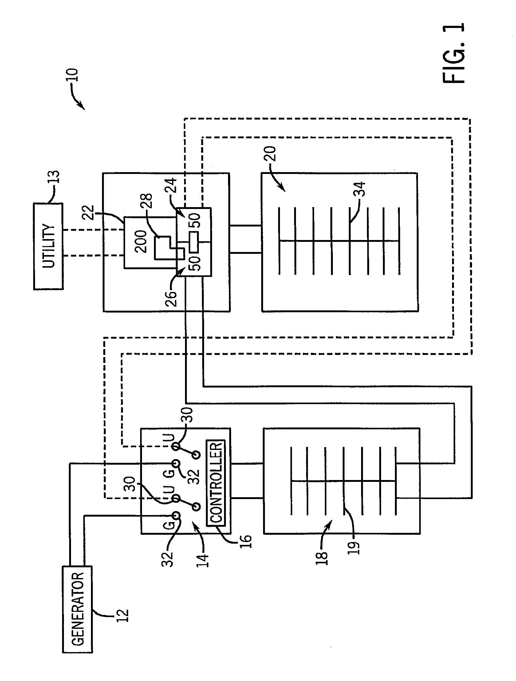
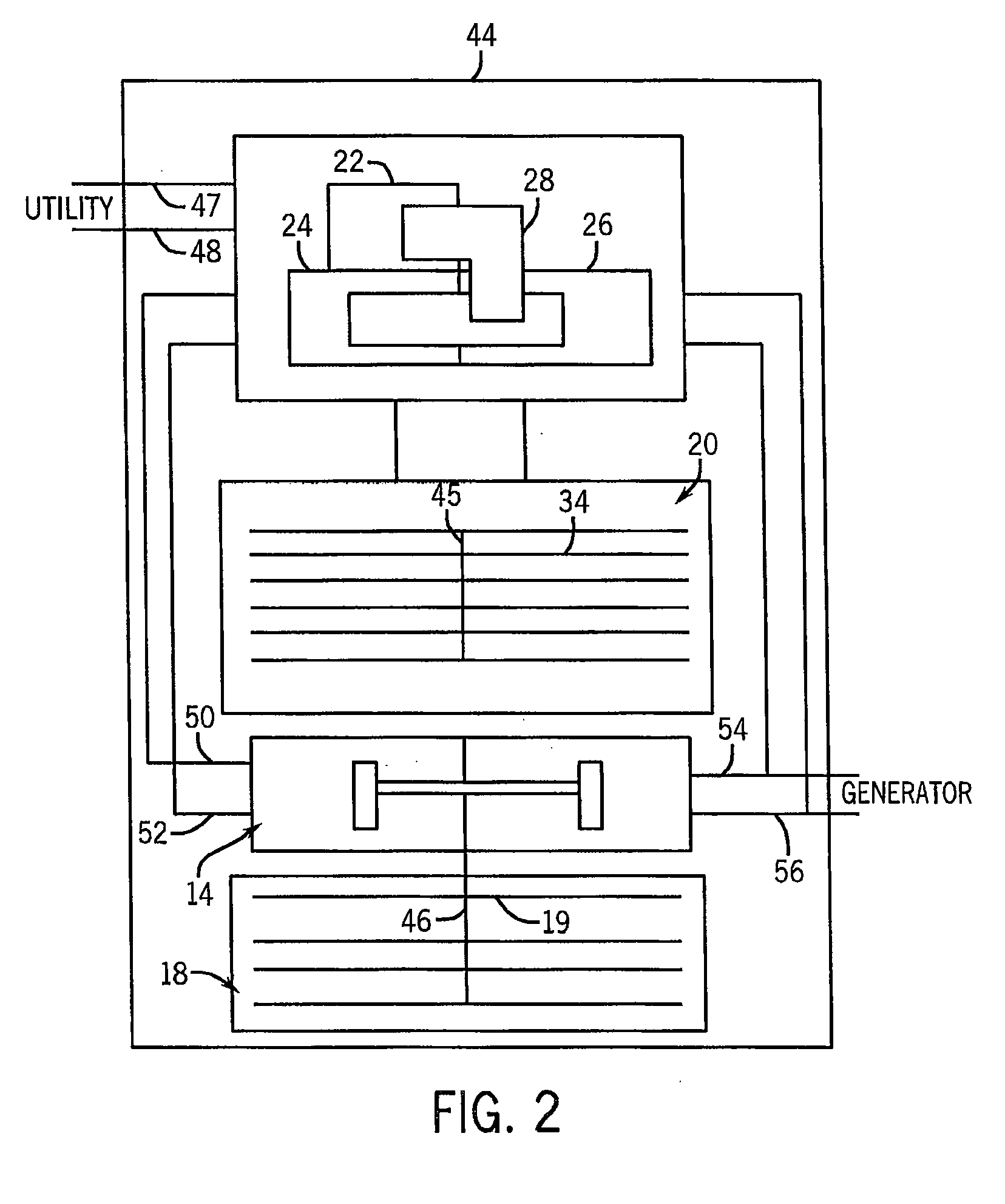
[0022]The invention is directed to a circuit and switch assembly that can be used in combination with an automatic transfer switch and generator package, in either a new installation or in a retrofit manner. The circuit and switch assembly is designed to allow any circuit, not just emergency or critical circuits, to be powered by an auxiliary power source, such as a generator, during primary power source failure. Insofar as the present invention relates to the automatic connection of critical or emergency loads to an auxiliary or auxiliary power source in the event of primary power source failure or disruption, such functionality is well-known in the art. For example, U.S. Pat. No. 7,119,457, the disclosure of which is incorporate herein by reference, describes a transfer switch that connects loads in order of priority to auxiliary power. It is understood that the present invention is applicable with such transfer switches and other transfer switches that provide automatic connectio...


PUM


Abstract

An electrical distribution system is designed to automatically connect a dedicated group of circuits, which are normally powered by a primary power source, to an auxiliary power source upon detection that there has been a disruption or failure in the primary power source. The system includes a switching arrangement that allows an operator to manually connect the auxiliary power source with other circuits that are not generally powered during disruption of the primary power source. The switching arrangement includes an interlinked switch or breaker arrangement that prevents any of the other circuits that are normally powered by the primary source from being automatically connected to the primary power source when primary power source is restored if those other circuits are connected to the auxiliary power source when the primary power source is restored.

Description

CROSS-REFERENCE TO RELATED APPLICATION[0001]The present application is a continuation-in-part of U.S. Ser. No. 12 / 133,942, filed Jun. 5, 2008, which is a continuation-in-part of U.S. Ser. No. 11 / 801,171, filed May 9, 2007, the disclosures of which are incorporated herein by reference.BACKGROUND OF THE INVENTION[0002]This invention relates generally to coordinating power delivery to critical and non-critical loads of a building or similar structure during main or primary power failure. More particularly, the present invention is directed to a transfer switch that allows circuits of a load center to be connected to an auxiliary power source when primary power fails.[0003]A building, such as a home or other dwelling, will present critical and non-critical loads to the primary power source to the building, which is generally a utility power supply. The critical loads for a home, for instance, may include the HVAC system, sump pump, refrigerators, freezers, dishwasher, washer / dryer, and ...

Claims


Application Information

Patent Timeline
Patent Type & Authority Applications(United States)
IPC IPC(8): H02J9/06
CPCH02J9/06
Inventor FLEGEL, MICHAEL O.FLEGEL, JEFFREY D.CZARNECKI, NEIL A.
Owner RELIANCE CONTROLS
Why Eureka
Try Eureka