Electric motor assembly with stator mounted in vehicle powertrain housing and method

a technology of electric motor and powertrain, which is applied in the manufacture of stator/rotor bodies, mechanical energy handling, and magnetic circuit shapes/forms/construction, etc., can solve problems such as stator misalignmen

Active Publication Date: 2009-08-27
GM GLOBAL TECH OPERATIONS LLC
View PDF13 Cites 56 Cited by
  • Summary
  • Abstract
  • Description
  • Claims
  • Application Information

AI Technical Summary

Benefits of technology

[0004]Differences in rates of thermal expansion among different materials used for a stator and a powertrain housing can cause a misalignment of the stator and rotor of an electric motor included in the powertrain. An inexpensive solution is provided to prevent relative motion between the stator and the housing. Specifically, an electric motor assembly in a vehicle powertrain is provided with a generally annular stator fit within an interior cavity defined by the motor housing. Roll pins are fit between the housing and the stator. Roll pins, sometimes referred to as spring pins, are elongated, generally cylindrical pins that may be compressed radially and are biased to maintain a radially-outward spring force. Thus, when the roll pins are fit between the housing and stator, as differences in rates of thermal expansion cause a gap of varying size between the stator and housing, the roll pins will expand and contract as necessary to maintain contact with the stator and housing at least over a predetermined gap distance.

Problems solved by technology

Differences in rates of thermal expansion among different materials used for a stator and a powertrain housing can cause a misalignment of the stator and rotor of an electric motor included in the powertrain.

Method used


Image

  • Electric motor assembly with stator mounted in vehicle powertrain housing and method
  • Electric motor assembly with stator mounted in vehicle powertrain housing and method
  • Electric motor assembly with stator mounted in vehicle powertrain housing and method

Examples


Embodiment Construction

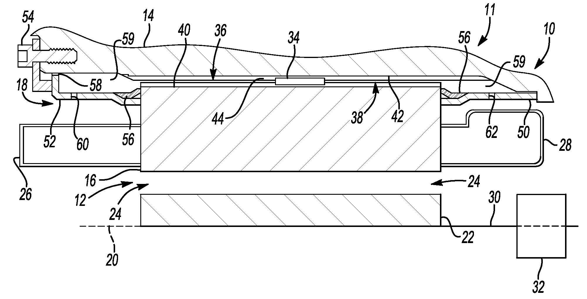
[0015]Referring to the drawings, wherein like reference numbers refer to like components, FIG. 1 shows a portion of an electrically-variable transmission 10 of a hybrid powertrain 11 that includes an electric motor assembly 12. The electric motor assembly 12 includes a housing 14, which in this case serves as both the motor housing and a transmission housing or casing. A transmission housing or casing houses the transmission gearing arrangement, such as transmission gearing arrangement 32 described below, as well as the motor assembly, unlike a separate motor housing which only houses a stator and rotor. The electric motor assembly 12 includes a generally annular steel stator 16 that is press-fit within an interior cavity 18 defined by the housing 14. Specifically, the stator 16 is a glued stack of punched silicon steel laminations. The stator 16 and housing 14 are shown in partial view, above an axis of rotation 20 of the transmission 10. Those skilled in the art will readily under...


PUM

PropertyMeasurementUnit
rates of thermal expansionaaaaaaaaaa
rate of thermal expansionaaaaaaaaaa
electrically-variableaaaaaaaaaa

Abstract

An electric motor assembly in a vehicle powertrain is provided with a generally annular stator fit within an interior cavity of the powertrain defined by a housing. Roll pins are fit between the housing and the stator. The stator may have a plurality of first geometric features and the housing a plurality of second geometric features. The first geometric features are be configured to align with the second geometric features when the stator is fit within the cavity, with the roll pins fit between the housing and the stator at the aligned first and second geometric features. A method of assembling the electric motor assembly is also provided.

Description

CROSS-REFERENCE TO RELATED APPLICATIONS[0001]This application claims the benefit of U.S. Provisional Application 61 / 031,482, filed Feb. 26, 2008, which is hereby incorporated by reference in its entirety.TECHNICAL FIELD[0002]The invention relates to an electric motor assembly and a method of assembling an electric motor in a vehicle powertrain; specifically, an electric motor stator fit within a vehicle powertrain housing with roll pins therebetween.BACKGROUND OF THE INVENTION[0003]Electric motors, such as those typically used in hybrid electromechanical powertrains for automotive vehicles, have a stator surrounding a rotor that is rotatable relative to the stator. The stator is grounded to a stationary member, such as a transmission housing or casing. It is important that the relative positions of the stator and rotor remain substantially constant in order to preserve a precisely sized gap between the stator and rotor. This is of special difficulty in the case of a vehicle transmis...

Claims


Application Information

Patent Timeline
Patent Type & Authority Applications(United States)
IPC IPC(8): H02K5/22H02K9/19H02K15/14
CPCH02K1/185H02K5/20Y10T29/49009H02K15/02H02K7/006H02K5/203
Inventor KINGMAN, GRANTLAND I.HOLMES, ALAN G.
Owner GM GLOBAL TECH OPERATIONS LLC
Why Eureka
Try Eureka