Hysteresis offset cancellation for magnetic sensors

a technology of magnetic sensors and offset cancellation, applied in the field of magnetic field sensors, can solve the problems of not being used for high-resolution sensor applications, and achieve the effect of hysteresis characteristics

Active Publication Date: 2009-08-27
ALLEGRO MICROSYSTEMS INC
View PDF52 Cites 47 Cited by
  • Summary
  • Abstract
  • Description
  • Claims
  • Application Information

AI Technical Summary

Benefits of technology

[0007]Embodiments of the invention may include one or more of the following features. The DC offset may be related to hysteresis characteristics of the MR sensing device. The MR sensing device may include a sensing element to sense the magnetic field and that sensing element may be a giant magnetoresistive (GMR) element, a magnetic tunnel junction (MTJ) element, a tunneling magnetoresistance (TMR) element or a anisotropic magnetoresistance (AMR) element. The circuitry may include a DC offset determiner to receive the AC signal voltage as an input and provide an averaged DC offset as an output. The circuitry may further include a device to subtract the averaged DC offset from the AC signal voltage to produce a sensor output signal. The DC offset determiner may include a positive peak detecting portion to produce a positive peak value, a negative peak detecting portion to produce a negative peak value, a summing block to produce a sum of the positive and negative peak values and an averaging circuit to divide the sum by two to produce the averaged DC offset. The positive peak detecting portion, the negative peak detecting portion, the summing block and the averaging circuit may operate in the digital domain. The positive and negative peak detecting portions may include a hold circuit to delay offset determination by the DC offset determiner for at least one clock cycle.

Problems solved by technology

The error resulting from the hysteresis takes the form of a direct current (DC) offset in the sensor output.
Although MR sensors such as GMR sensors generally offer higher sensitivity than other types of magnetic field sensors, for example, Hall Effect sensors, they are not presently used for high resolution sensor applications because of their hysteresis characteristics.

Method used


Image

  • Hysteresis offset cancellation for magnetic sensors
  • Hysteresis offset cancellation for magnetic sensors
  • Hysteresis offset cancellation for magnetic sensors

Examples


Embodiment Construction

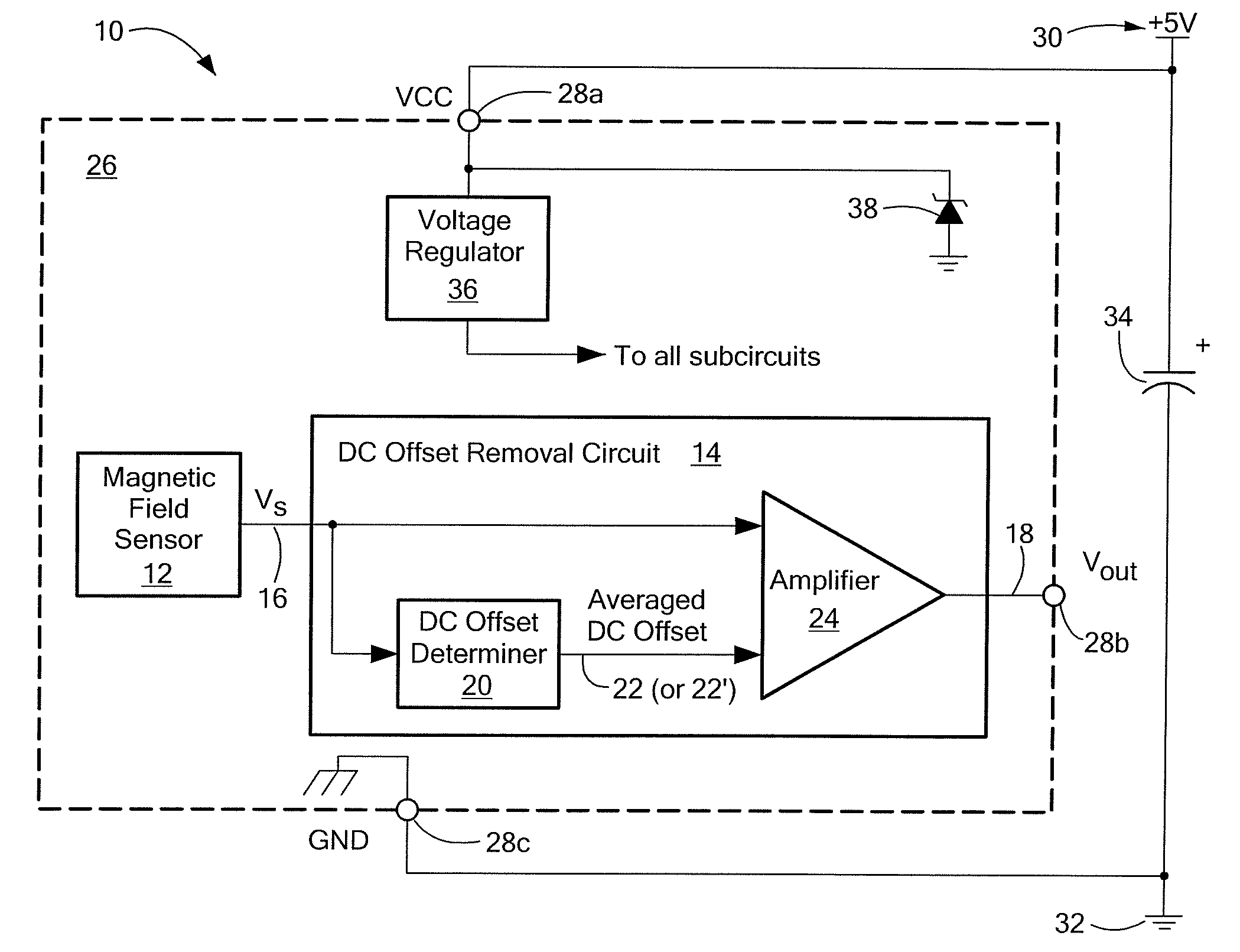
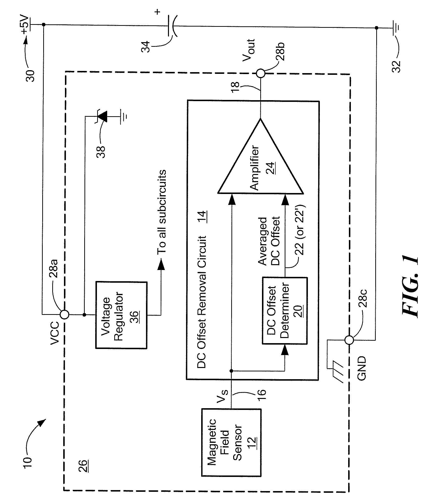
[0020]Referring to FIG. 1, a sensor 10 that includes a magnetic field sensor 12 coupled to a DC offset removal circuit 14 is shown. The magnetic field sensor 12 converts a sensed magnetic field into an AC signal voltage, shown as a sensed voltage Vs 16, that is proportional to the sensed magnetic field. The DC offset removal circuit 14 receives as input the voltage Vs 16 measured by the magnetic sensor 12 and provides at the sensor output an AC signal voltage (shown as output voltage Vout 18) that has been adjusted for DC offset. The DC offset removal circuit 14 serves to remove DC offset associated with sensing the magnetic field, in particular, DC offset related hysteresis characteristics of the magnetic field sensor 12. For example, and as will be described more fully below, when the magnetic field sensor 12 employs some type of magnetoresistive (MR) sensing device, the DC offset is a hysteresis-induced DC offset.

[0021]An ideal sensor operation is one in which the measured AC sig...


PUM


Abstract

Presented is a sensor that includes a magnetoresistive (MR) sensing device to sense a magnetic field and to produce an AC signal voltage proportional to the sensed magnetic field. The sensor also includes circuitry, coupled to the MR sensing device, to remove DC offset from the AC signal voltage. The DC offset may be related to the hysteresis characteristics of the MR sensing device. To remove DC offset, the circuitry may obtain an averaged DC offset and subtract the averaged DC offset from the AC signal voltage to produce a sensor output signal.

Description

CROSS-REFERENCE TO RELATED APPLICATIONS[0001]Not applicable.STATEMENT REGARDING FEDERALLY SPONSORED RESEARCH[0002]Not applicable.FIELD OF THE INVENTION[0003]This invention relates generally to magnetic field sensors and, in particular, magnetic field sensors that utilize magnetoresistive (MR) sensing elements.BACKGROUND OF THE INVENTION[0004]All magnetic materials have hysteresis. Hysteresis, specifically, magnetic hysteresis, refers to the history dependent nature of the magnetic field applied to the material. Because a magnetoresistive (MR) sensor such as a giant magnetoresistive (GMR) sensor is made of magnetic material, its response exhibits the effects of hysteresis. A plot of resistance against applied magnetic field forms a hysteresis loop, as the change in resistance in the forward direction (for increasing applied magnetic field) and the reverse direction (for decreasing applied magnetic field) are not the same. The hysteresis loop thus shows that the resistance doesn't jus...

Claims


Application Information

Patent Timeline
Patent Type & Authority Applications(United States)
IPC IPC(8): G01R33/09
CPCG01R15/202G01R15/205G01R15/207G01R33/09G01R33/0029G01R33/0035G01R33/0023
Inventor CUMMINGS, JOHNTAYLOR, WILLIAM P.HAAS, DAVID J.
Owner ALLEGRO MICROSYSTEMS INC
Why Eureka
Try Eureka