
Eureka
For R&D, Eureka makes reading and utilizing patents & technical documents easy.
Eureka AIR
Designed for self-driven R&D workflows. Generate viable solutions, solve complex R&D challenges, empower your innovation with AI.

Eureka Materials
Designed for material experts only. Revolutionize your material R&D, from search, analyze, to developing new materials.

TechResearch
Generate reliable direction feasibility study reports for your R&D in just a few steps.

TechSeek
Discover and master advanced knowledge NOW. Basics, ideas, possibilities, all at once.

TechMind
As an expert in R&D Theories, TechMind can generates customized viable solutions instantly.

TechRisk
Analyze your overall solution with one click, know your potential R&D risks in advance.

TechMonitor
Get weekly tech updates, stay abreast of the latest tech innovations and key insights.
Image forming apparatus and image forming method
- Summary
- Abstract
- Description
- Claims
- Application Information
AI Technical Summary
Benefits of technology
Problems solved by technology
Method used
Image

Examples
first embodiment
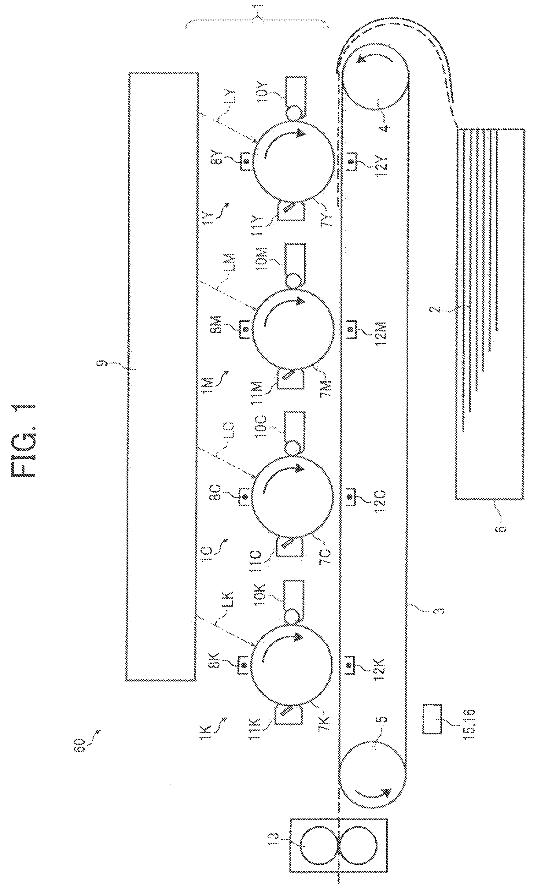
[0059]A principle of image forming to be performed by a color copier 60 according to the present invention will be described with reference to FIG. 1. As shown in FIG. 1, the color copier 60 includes an image forming unit 1, an exposure unit 9, and a transfer belt 3. The color copier 60 forms images on a transfer sheet by using the technique of electrophotography.
[0060]The color copier 60 is a what is called tandem-type image forming apparatus, moreover, the color copier 60 employs a direct transfer method. In this color copier 60, image forming units 1Y, 1M, 1C, and 1K that form images (toner images) of four colors (yellow (Y), magenta (M), cyan (C), and black (K)) are linearly arranged in the direction of movement of the endless transfer belt 3. The transfer belt 3 conveys a transfer sheet 2 sequentially from under the image forming unit 1Y to the image forming unit 1K. The image forming units 1Y, 1M, 1C, and 1K are parts of the image forming unit 1. Meanwhile, in the following de...
second embodiment
[0172]A density correcting unit 1505a, which can be used in place of the density correcting unit 1505 shown in FIG. 28, calculates a density correction value for use in correction of a target-pixel color density by using the neighboring-pixel color densities determined by the density-distribution determining unit 1504. The density correction value depends on an area on the correction target pixel to be covered by a toner image that would be formed based on the color densities of image data to be represented by the neighboring pixels. The density correcting unit 1505a corrects the target-pixel color density by using the calculated density correction value.
[0173]For example, when the shift direction is “down”, the density correcting unit 1505a calculates the density correction value by using Equation (1):
a=−1 / 15×(4×x+Σy(n))+1 (1)
[0174]where a: density correction value[0175]x: target-pixel color density[0176]y(n): neighboring-pixel color density (n=1: upper neighboring pixel, n=2: l...
third embodiment
[0180]In the third embodiment, the RAM 123 stores therein determination patterns, shift directions, and density correction values that are mapped to one another. Each of the determination patterns shows a pixel arrangement in which a pixel of interest on a shift position is a noise-inducing pixel. The noise-inducing pixel leads to local color density change because of a change in relationship with an adjacent pixel of the noise-inducing pixel. The density correction value is for use in correction of a target-pixel density value and depends on an area on the correction target pixel to be covered by a toner image that would be formed based on color densities of image data to be represented by neighboring pixels of the correction target pixel.
[0181]FIG. 47 is a block diagram of a noise-correction processing unit 1353a, which can be used in place of the noise-correction processing unit 1353 shown in FIG. 27, according to the third embodiment. FIG. 48 is a flowchart for explaining how th...
PUM
 Abstract
Description
Claims
Application Information
 - R&D Engineer
- R&D Manager
- IP Professional
- Industry Leading Data Capabilities
- Powerful AI technology
- Patent DNA Extraction
Browse by: Latest US Patents, China's latest patents, Technical Efficacy Thesaurus, Application Domain, Technology Topic, Popular Technical Reports.
© 2024 PatSnap. All rights reserved.Legal|Privacy policy|Modern Slavery Act Transparency Statement|Sitemap|About US| Contact US: help@patsnap.com