
Radio detection device and method

a detection device and a technology for radio detection, applied in the direction of amplitude demodulation, transmission monitoring, instruments, etc., can solve the problems of high resolution a/d conversion circuit cost increase, angle calculation error, angle calculation error, etc., and achieve the effect of improving accuracy

Inactive Publication Date: 2009-08-27
OMRON AUTOMOTIVE ELECTRONICS CO LTD
View PDF9 Cites 8 Cited by
  • Summary
  • Abstract
  • Description
  • Claims
  • Application Information

AI Technical Summary

Benefits of technology

[0011]In the conventional mono-pulse radar, a high resolution A / D conversion circuit is used to enhance the measurement accuracy. The cost increases in the high resolution A / D conversion circuit by the high resolution, and as a result, the cost of the mono-pulse radar increases.
[0012]One or more embodiments of the present invention embodies a mono-pulse radar in which the accuracy is enhanced without using a high resolution A / D conversion circuit.
[0027]Therefore, according to one or more embodiments of the present invention, an object can be detected using the mono-pulse method. In particular, the mono-pulse radar with enhanced accuracy can be embodied.

Problems solved by technology

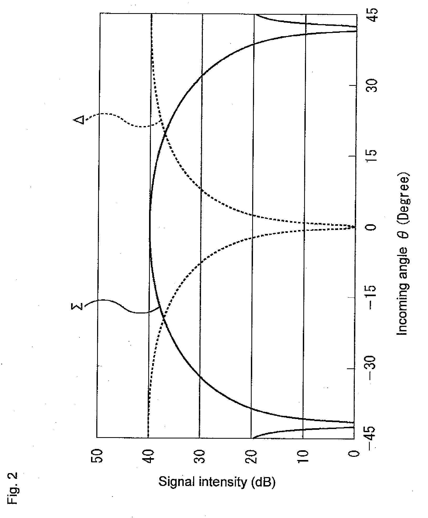
However, since the signal intensity of the sum signal Σ and the difference signal Δ changes about 40 dB, if the change in the signal amplitude with respect to an input range is significantly small in an A / D conversion process, there is no change or small variation in width in the discretized value after the A / D conversion, and an error occurs in the angle calculation.
If the signal amplitude is over the input range of the A / D conversion, the value after the A / D conversion saturates at the upper limit, and error occurs in the angle calculation.
The cost increases in the high resolution A / D conversion circuit by the high resolution, and as a result, the cost of the mono-pulse radar increases.

Method used


Image

  • Radio detection device and method
  • Radio detection device and method
  • Radio detection device and method

Examples


Embodiment Construction

[0035]An embodiment of the present invention will be described with reference to the drawings.

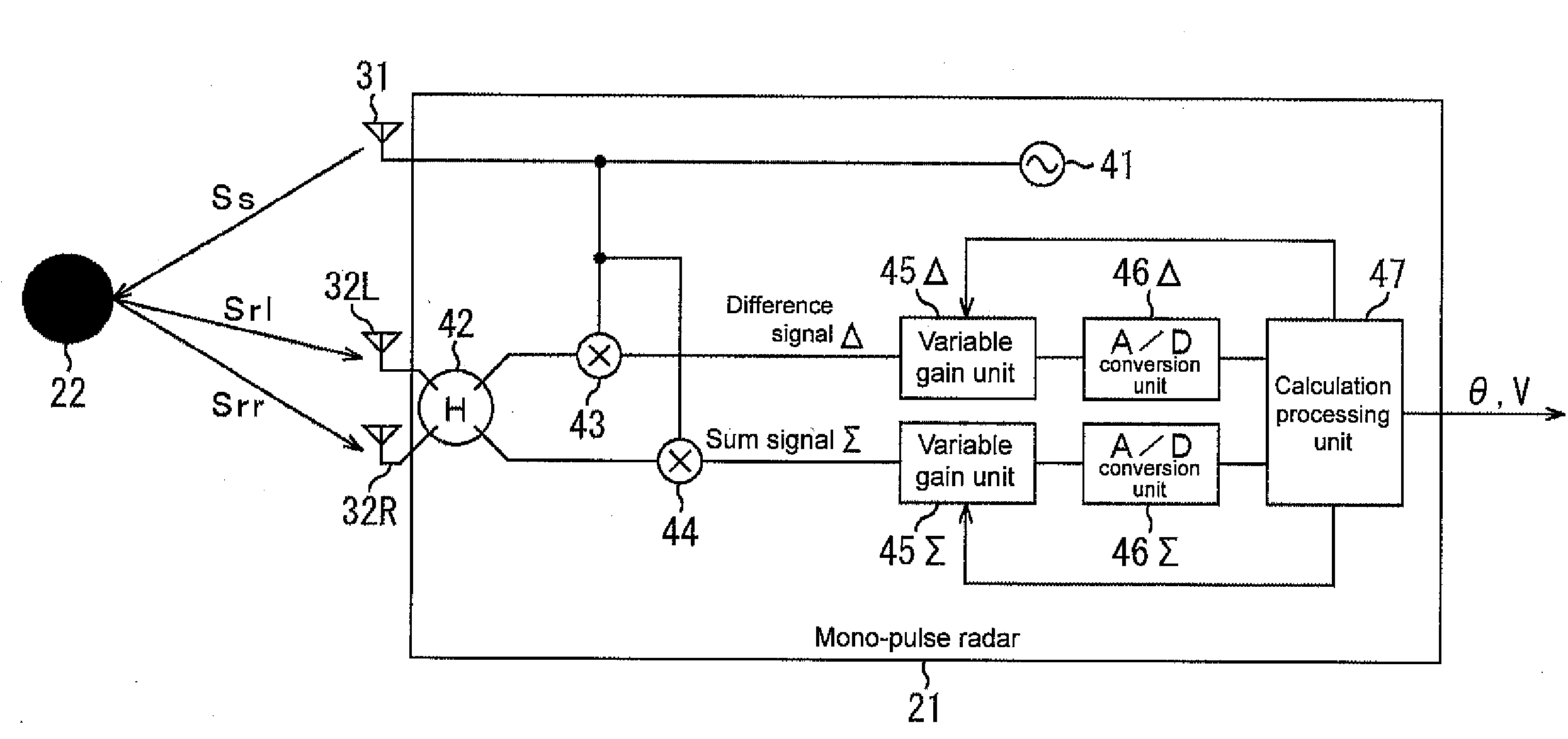
[0036]FIG. 3 shows a function block diagram showing a function of a mono-pulse radar 21 serving as a radio detection device applied with one or more embodiments of the present invention.

[0037]A transmission antenna 31 and two reception antennas 32L, 32R are arranged as antennas of the mono-pulse radar 21.

[0038]A transmission signal generation unit 41 generates a transmission signal Ss. The transmission signal Ss is transmitted from the antenna 31. The mode of the transmission signal Ss generated by the transmission signal generation unit 41 is not particularly limited as long as a phase difference can be obtained from the reception signal. For instance, CW, two-frequency CW, FMCW, and the like can be used.

[0039]The transmission signal Ss is reflected by a detecting object 22, and a reflected signal is received by the reception antenna 32L as a reception signal Srl and received by the recept...


PUM


Abstract

A radio detection device includes two or more reception antennas, for detecting a detecting object by a mono-pulse method; the radio detection device including: a variable gain unit for discretely changing respective signal intensity of a difference signal and a sum signal of each reception signal received by the two or more reception antennas; an A / D conversion unit for performing A / D conversion process on the difference signal or the sum signal, the difference signal or the sum signal having the signal intensity changed by the variable gain unit; an angle calculating portion for calculating an angle by the mono-pulse method using the difference signal and the sum signal after the A / D conversion process by the A / D conversion unit; and a control unit for performing a control of individually switching a conversion magnification of the signal intensity by the variable gain unit with respect to the difference signal and the sum signal.

Description

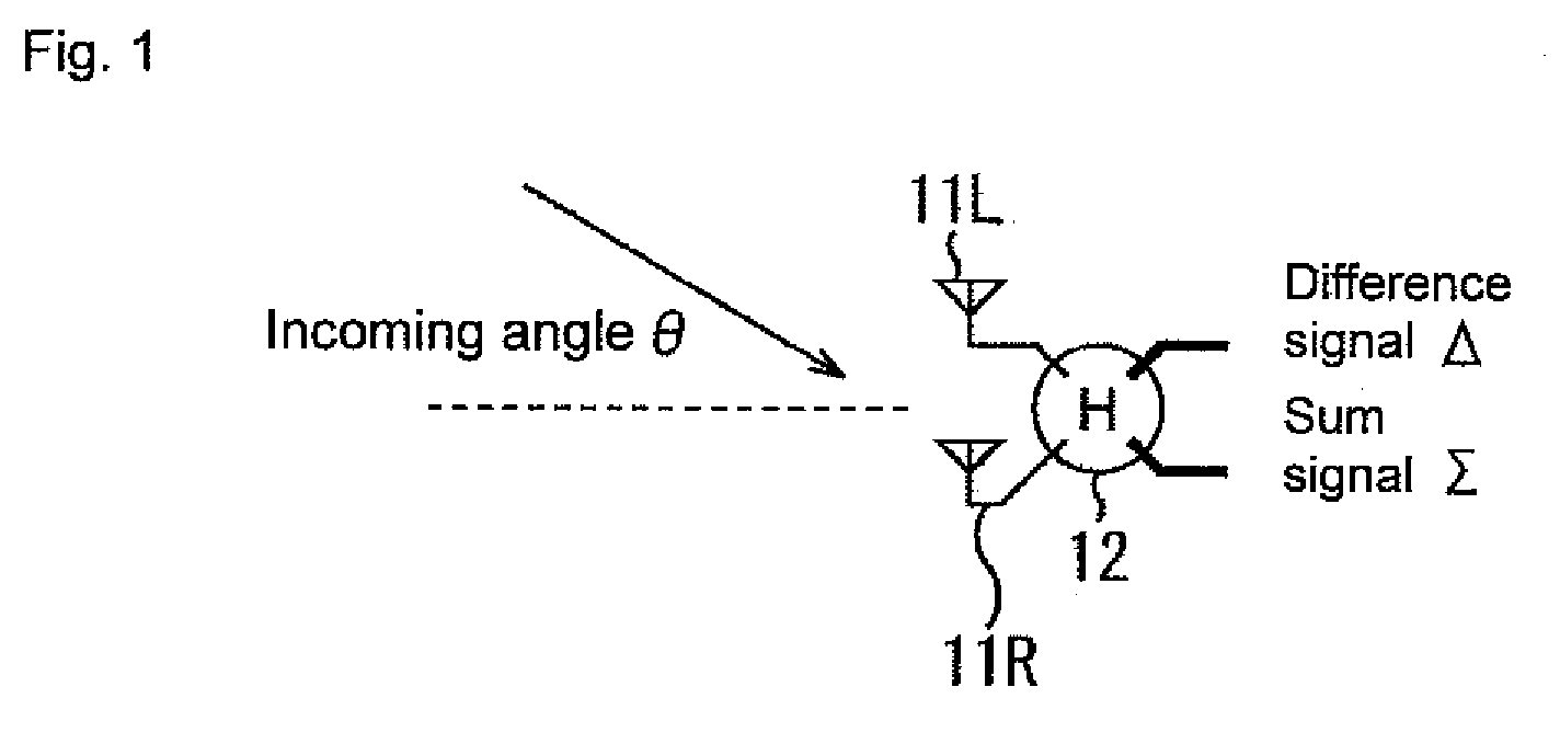
BACKGROUND OF THE INVENTION[0001]1. Technical Field[0002]The present invention relates to radio detection devices and methods, in particular, to a radio detection device and method with enhanced accuracy.[0003]2. Related Art[0004]Conventionally, a mono-pulse radar is mounted on an own vehicle as a radio detection device (radar) for detecting another vehicle having a possibility of colliding to avoid collision between the own vehicle and the another vehicle (refer to, for example, Japanese Patent Application Laid-Open No. H09-90026, Japanese Patent Application Laid-Open No. H06-150195).[0005]The mono-pulse type is one type of performing angle detection. That is, the mono-pulse radar detects an angle of a detecting object with respect to his / her center direction on the front side. In other words, if the mono-pulse radar is mounted at a front portion of the own vehicle, another vehicle on the front side of the own vehicle becomes the detecting object, and the angle of the another vehic...

Claims


Application Information

Patent Timeline
Patent Type & Authority Applications(United States)
IPC IPC(8): H03D1/24H04B17/00
CPCG01S3/32
Inventor NISHIDAI, TETSUOOHARA, HIDEYUKIICHIYANAGI, HOSHIBUMINUMATA, HIROYUKI
Owner OMRON AUTOMOTIVE ELECTRONICS CO LTD
Learn More