Fuel nozzles

a technology of fuel nozzles and nozzles, which is applied in the direction of combustion types, machines/engines, lighting and heating apparatus, etc., can solve the problems of varying the combustion air to fuel ratio and having possible detrimental effects on engine emissions

Inactive Publication Date: 2009-09-03
ROLLS ROYCE PLC
View PDF9 Cites 14 Cited by
  • Summary
  • Abstract
  • Description
  • Claims
  • Application Information

AI Technical Summary

Problems solved by technology

Unfortunately, such wider diameter fuel / air swirler arrangements results in a situation where these lean burn swirler arrangements are wider than the cross-section of the diffuser air flow jet.
In such circumstances, portions of the air flow have a depleted or lower pressure compared to central direct impingement portions of the air flow such that there is differential air / fuel mixing across the fuel injector and this in turn may lead to varying combustion air to fuel ratio with possible detrimental effects upon emissions from the engine.
These problems occur whether the fuel is presented to the air flow as a film or by direct fuel injection through jet apertures.

Method used


Image

  • Fuel nozzles
  • Fuel nozzles
  • Fuel nozzles

Examples


Embodiment Construction

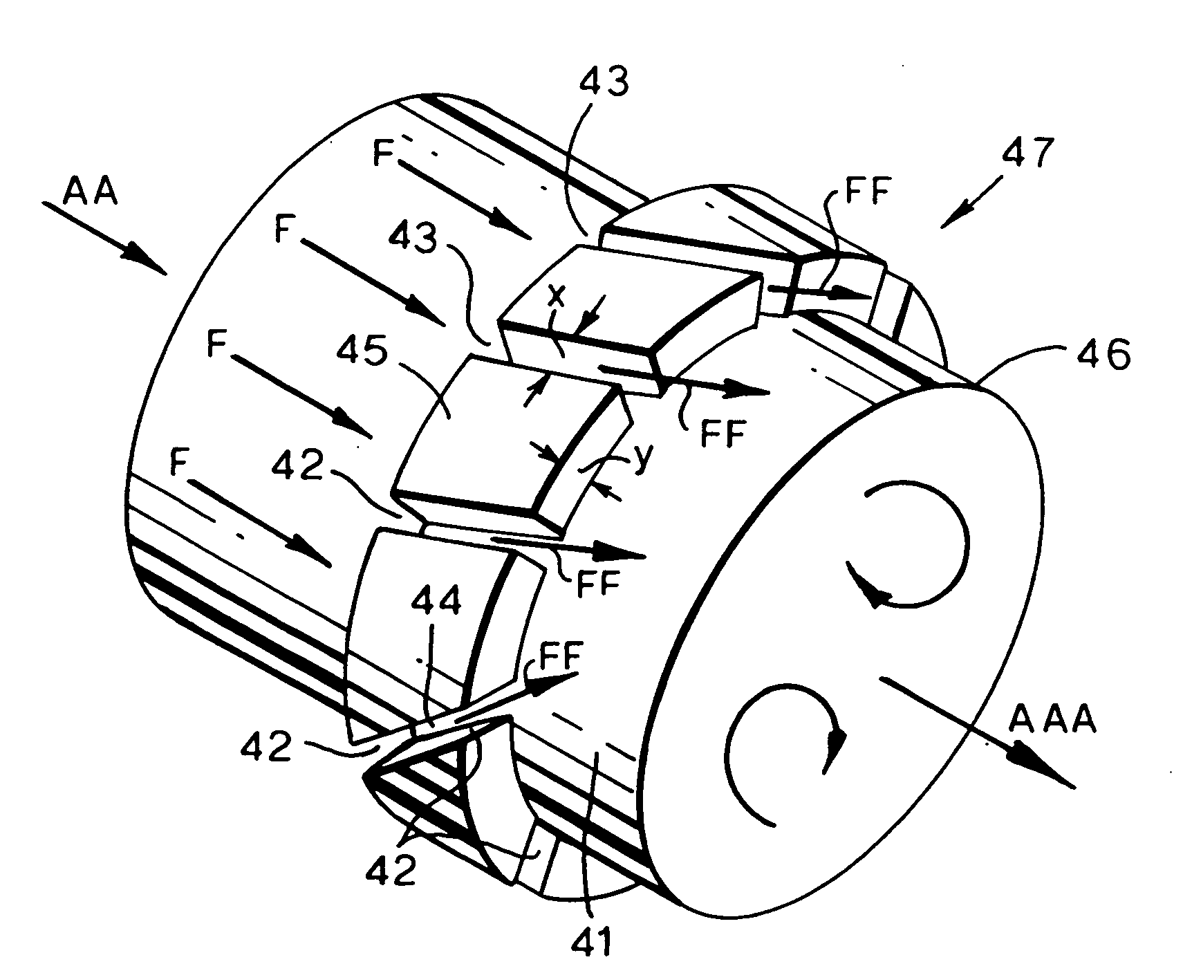
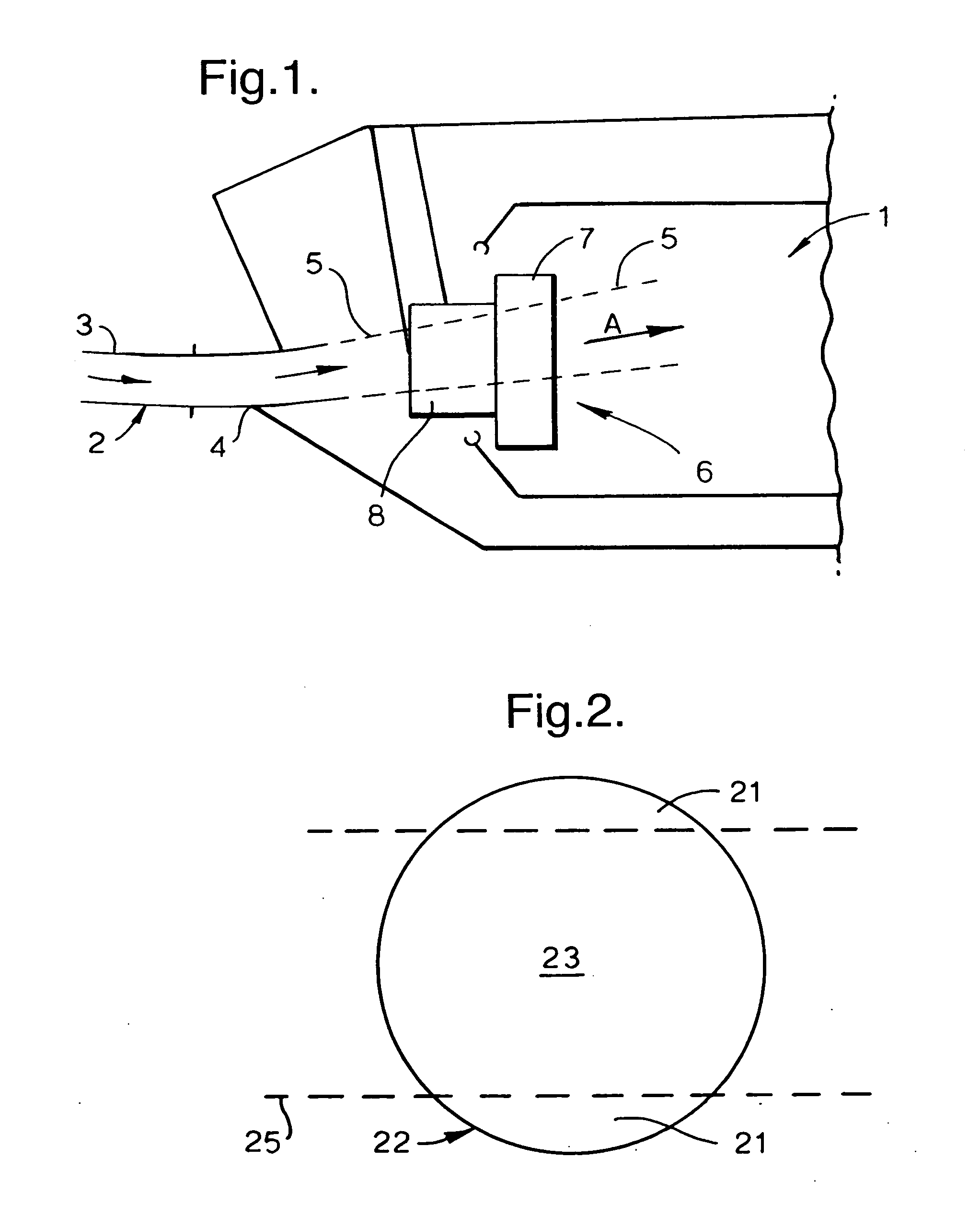
[0019]FIG. 1 schematically illustrates a combustion chamber 1 of an engine. The combustion chamber 1 is coupled to air coming from an upstream compressor via an air flow conduit 2 which comprises a passage 3 which leads to a diffuser 4 which in turn presents an air flow 5 to a fuel injection nozzle 6 in the direction of arrowhead A. An injection nozzle is substantially cylindrical with substantially circular upstream and downstream faces. The combustor is annular in form with a plurality of injection nozzles 6 arranged at uniform circumferential spacing around the annulus. The diffuser 4, which is a diverging channel, is also annular such that the air flow 5 takes the form of an annular ring of air flow in the direction of arrowhead A. This annular ring of air flow impinges upon the nozzle 6 whereby the swirl vanes 7 create air flow vorticity and turbulence to allow intermingling with fuel delivered in an injector portion 8 of the nozzle 6. It will be appreciated that it is the turb...


PUM


Abstract

In order to achieve better fuel distribution despite an oversized fuel injector nozzle relative to the impingement cross-section of an air flow directed towards that nozzle, an asymmetric distribution of fuel is provided. This asymmetric distribution is achieved by providing fuel distribution structures about the injector nozzle which present varying amounts of fuel to the air flow dependent upon the localised flow pressure in the air flow presented to the nozzle. Such asymmetric distribution of fuel is achieved by providing passages or jets of varying cross-section or distribution/spacing at different parts of the fuel injection nozzle dependent upon incident flow pressure. Thus, both parts of the injector nozzle directly impinged by the air flow generally present more fuel to that flow compared to depleted flow pressure zones of the air flow.

Description

FIELD OF THE INVENTION[0001]The present invention relates to fuel nozzles and more particularly to fuel nozzles used with regard to gas turbine engines associated with aircraft.BACKGROUND OF THE INVENTION[0002]There is an on-going objective to minimise noxious emissions from engines and noise in order to render such engines more environmentally acceptable. In such circumstances, it is necessary to ensure that the fuel / air mix within the engine is appropriately regulated to achieve the desired emissions objectives. Typically, as described in U.S. patent publication No. 2002 / 0134084 (Parker-Hannifin Corporation) fuel is presented to a swirling air flow in order to create an even distribution and therefore appropriate combustion within an engine.[0003]In the injector described in US2002 / 0134084, the air flow from the engine compressor is entrained and passes through a diffuser such that its jet output cross-section is substantially the same width as or greater than the inlet for the fu...

Claims


Application Information

Patent Timeline
Patent Type & Authority Applications(United States)
IPC IPC(8): F02C7/22
CPCF23D11/107F23R3/28F23D2900/11101F23D14/58
Inventor YOUNG, KENNETH J.
Owner ROLLS ROYCE PLC
Why Eureka
Try Eureka