Ultrasonic probe, ultrasonic testing equipment, ultrasonic testing method, and manufacturing method of seamless pipe or tube

a technology of ultrasonic testing and manufacturing methods, applied in the direction of instruments, specific gravity measurement, measurement devices, etc., to achieve the effect of high precision, rapid detection and high precision

Active Publication Date: 2009-09-03
NIPPON STEEL CORP
View PDF8 Cites 41 Cited by
  • Summary
  • Abstract
  • Description
  • Claims
  • Application Information

AI Technical Summary

Benefits of technology

[0021]The present invention has been developed to solve such problems of conventional technologies, and it is an object of the present invention to provide an ultrasonic probe, an ultrasonic testing equipment and an ultrasonic testing method capable of quickly detecting flaws having various tilt angles with respect to an axial direction of a tubular test object with high precision, and a manufacturing method of a seamless pipe using the probe, apparatus and method.
[0083]According to the preferable invention, since the positioning mechanism is controlled (the position of the ultrasonic probe is adjusted), based on the distance up to the ultrasonic probe and the external surface of the tubular test object calculated using the non-contact displacement gauge that is not in contact with the tubular test object, so that the relative position of the ultrasonic probe with respect to the tubular test object is approximately constant, compared with the above case where the contact-type displacement gauge is adopted, better tracking can be obtained and, as a result, excellent detectability of the flaw can be obtained.

Problems solved by technology

Problems of the above-described conventional technologies are not limited to a case where a test object is a seamless pipe, but are common to ultrasonic testing of all types of tubular test objects in which tilted flaws may occur including a welded pipe such as a spiral pipe, and a hollow axle.

Method used


Image

  • Ultrasonic probe, ultrasonic testing equipment, ultrasonic testing method, and manufacturing method of seamless pipe or tube
  • Ultrasonic probe, ultrasonic testing equipment, ultrasonic testing method, and manufacturing method of seamless pipe or tube
  • Ultrasonic probe, ultrasonic testing equipment, ultrasonic testing method, and manufacturing method of seamless pipe or tube

Examples


first embodiment

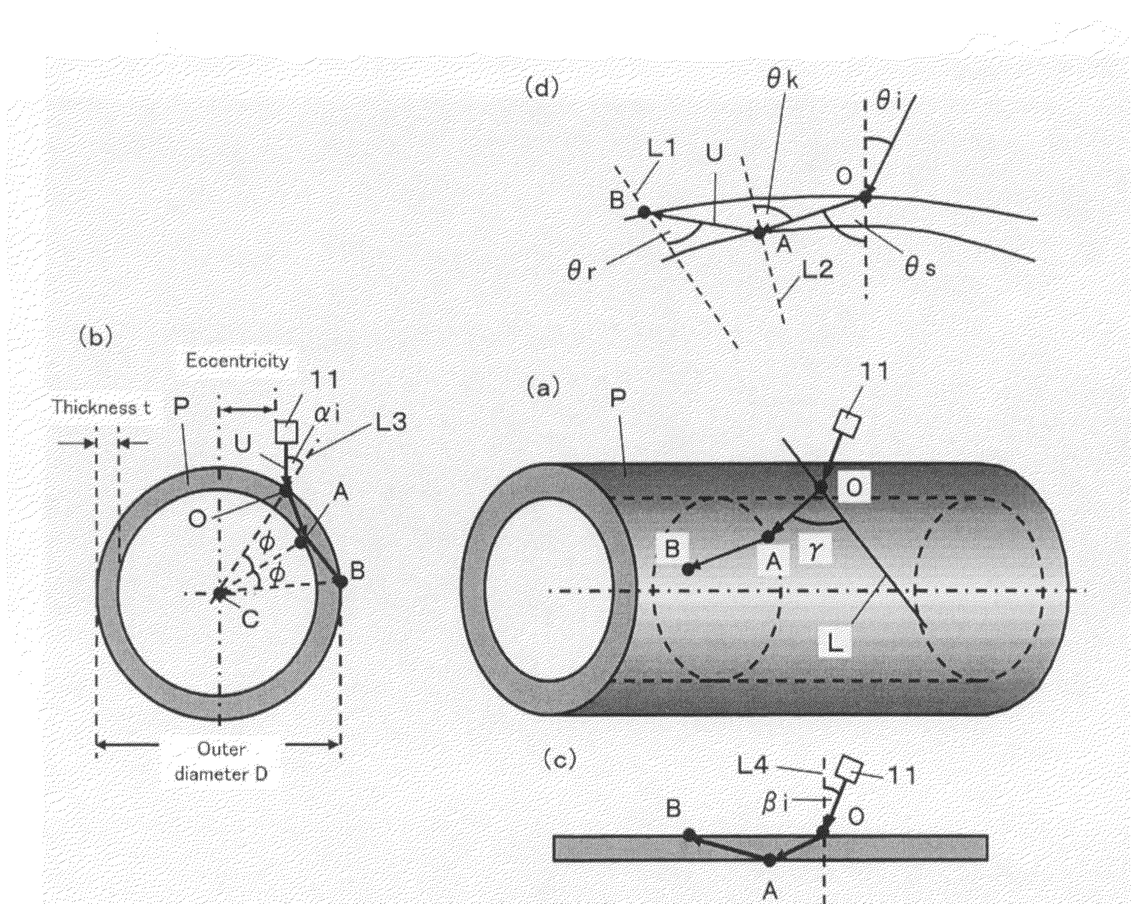
[0103]FIG. 3 is a schematic diagram showing an outline configuration of an ultrasonic testing equipment according to the first embodiment of the present invention, and FIG. 2 is an illustration showing propagation behavior of an ultrasonic wave in the ultrasonic testing equipment shown in FIG. 3. FIG. 4 (a) shows a perspective view, FIG. 4 (b) shows a sectional view in a circumferential direction of a pipe, FIG. 4 (c) shows a sectional view in an axial direction of a pipe, and FIG. 4 (d) shows a sectional view along a propagation plane (plane containing points O, A, and B shown in FIG. 4 (a)) of ultrasonic waves. As shown in FIG. 3, an ultrasonic testing equipment 100 according to the present embodiment is an ultrasonic testing equipment for detecting a flaw in a pipe P having an ultrasonic probe 1 in which a plurality of transducers 11 are arranged in a row direction and a column direction respectively in a matrix state (arranged on a cylinder curved in the row direction in a matri...

second embodiment

[0118]FIG. 5 is a schematic diagram showing the outline configuration of an ultrasonic testing equipment according to the second embodiment of the present invention. FIG. 5 (a) shows a perspective view, FIG. 5 (b) shows a plan view, FIG. 5 (c) shows a side view, and FIG. 5 (d) shows an illustration. FIG. 6 is an illustration showing propagation behavior of an ultrasonic wave in the ultrasonic testing equipment shown in FIG. 5. FIG. 6 (a) shows a perspective view, FIG. 6 (b) shows a sectional view in a circumferential direction of a pipe, FIG. 6 (c) shows a plan view, and FIG. 6 (d) shows a sectional view along a propagation plane (plane containing points O, A, and B shown in FIG. 6 (b)) of ultrasonic waves. As shown in FIG. 5, an ultrasonic testing equipment 100A according to the present embodiment is, like the ultrasonic testing equipment 100 according to the first embodiment, an ultrasonic testing equipment for detecting a flaw in the pipe P having an ultrasonic probe 1A and a tra...

example 1

See FIG. 3

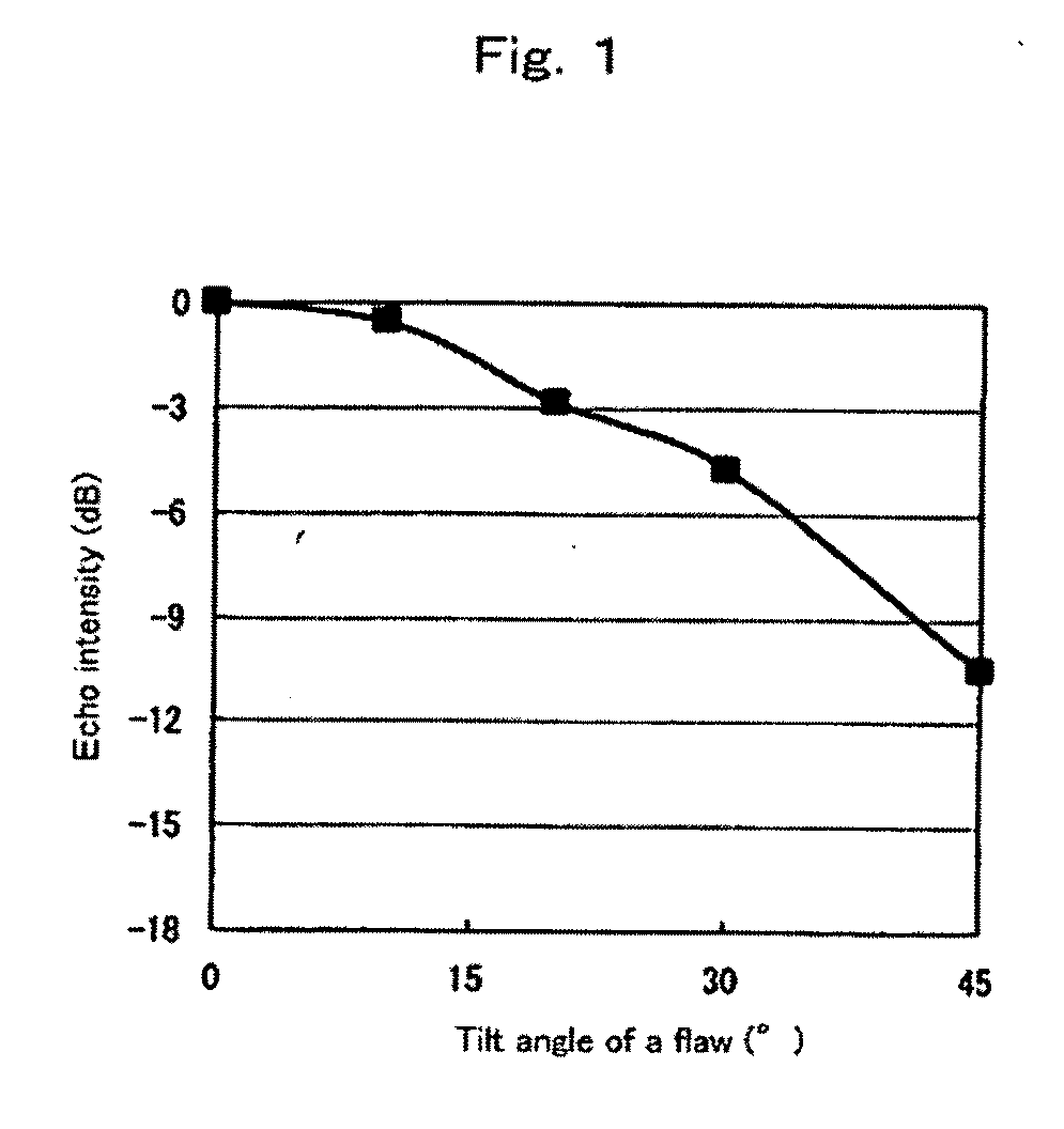
[0153]Using the ultrasonic testing equipment 100 whose outline configuration is shown in FIG. 3, an ultrasonic testing of a plurality of internal surface flaws (depth 0.5 mm X length 25.4 mm) with mutually different tilt angles (tilt angles of 0°, 10°, 20°, 30°, and 45°) formed on the internal surface of a steel pipe was carried out. Here, the ultrasonic probe 1 has a plurality (30) of transducers 11 of length 5 mm×width 3 mm with oscillating frequency 2 MHz arranged on a cylinder curved with a radius of curvature of 200 mm in a matrix state (10 rows×3 columns) in the row direction (axial direction of the steel pipe). When deemed appropriate below, transducers 11 arranged in the first column are called #1 to #10, transducers 11 arranged in the second column are called #11 to #20, and transducers 11 arranged in the third column are called #21 to #30.

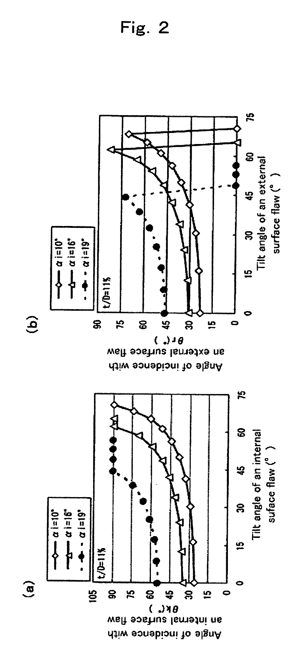
[0154]Table 1 shows the axial angle of incidence βi, the propagation direction γ, and the internal refraction angle θk of an u...


PUM

PropertyMeasurementUnit
depthaaaaaaaaaa
sizeaaaaaaaaaa
circumferential angleaaaaaaaaaa

Abstract

The ultrasonic testing method according to the invention includes the steps of arranging an ultrasonic probe 1 having a plurality of transducers 11 so as to face a tubular test object P, and causing the transducers appropriately selected from the plurality of transducers to transmit and receive ultrasonic waves so that the ultrasonic waves are propagated in the tubular test object in a plurality of different propagation directions, wherein a ultrasonic testing condition by the ultrasonic probe is set so that respective external refraction angles θr of the ultrasonic waves in the plurality of propagation directions are approximately equivalent and / or respective internal refraction angles θk of the ultrasonic waves in the plurality of propagation directions are approximately equivalent.

Description

TECHNICAL FIELD[0001]The present invention relates to an ultrasonic probe, an ultrasonic testing equipment and an ultrasonic testing method for detecting a flaw existing on a tubular test object such as a steel pipe or tube using an ultrasonic wave, and a manufacturing method of a seamless pipe or tube using the method, and in particular, to an ultrasonic probe, an ultrasonic testing equipment and an ultrasonic testing method capable of quickly detecting flaws having various tilt angles with respect to an axial direction of a tubular test object with high precision, and a manufacturing method of a seamless pipe or tube using the method.BACKGROUND ART[0002]As demand for higher quality pipes or tubes grows in recent years, there is an increasing trend that nondestructive test standards for the pipes or tubes (hereinafter referred to as “pipes” when deemed appropriate) are becoming more stringent.[0003]For example, a seamless pipe, which is a typical pipe, is manufactured by punching a...

Claims


Application Information

Patent Timeline
Patent Type & Authority Applications(United States)
IPC IPC(8): G01N29/04
CPCG01N29/043G01N29/2487G01N29/262G01N29/265G01N2291/2634G01N2291/0421G01N2291/0422G01N2291/056G01N2291/106G01N2291/0289
Inventor YAMANO, MASAKI
Owner NIPPON STEEL CORP
Why Eureka
Try Eureka