

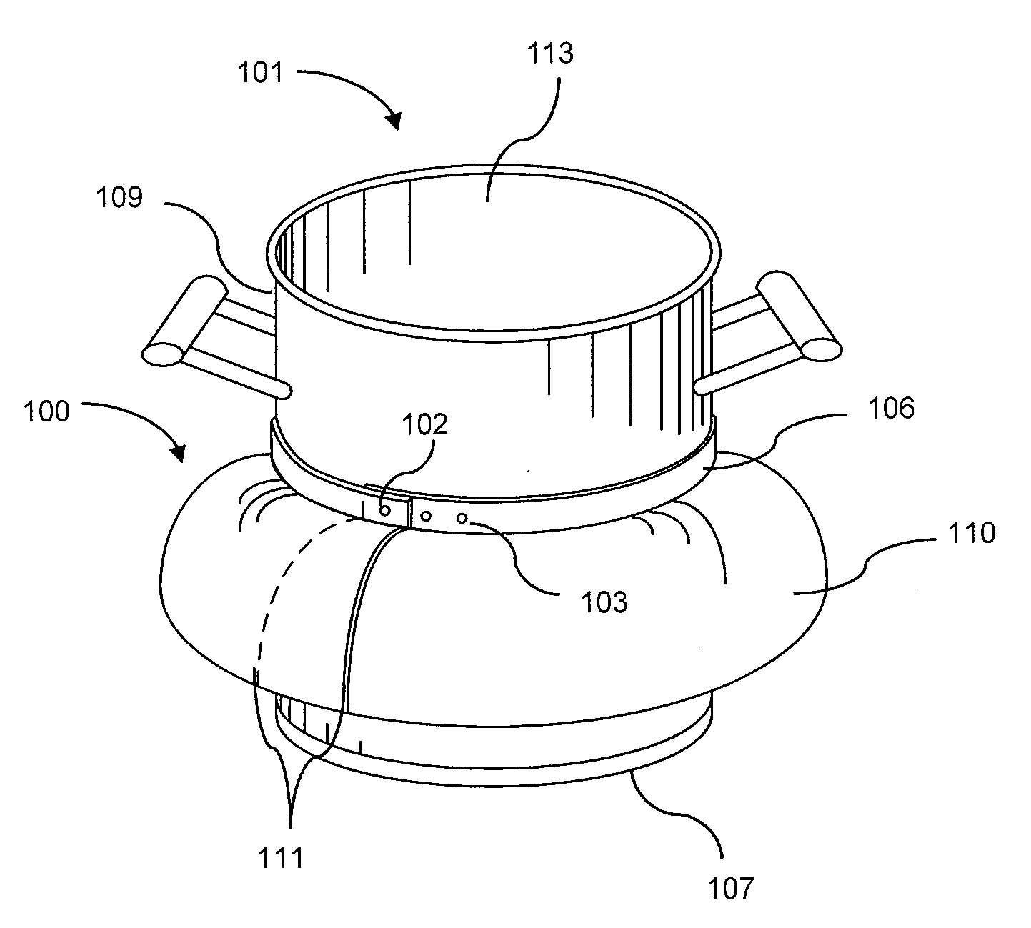
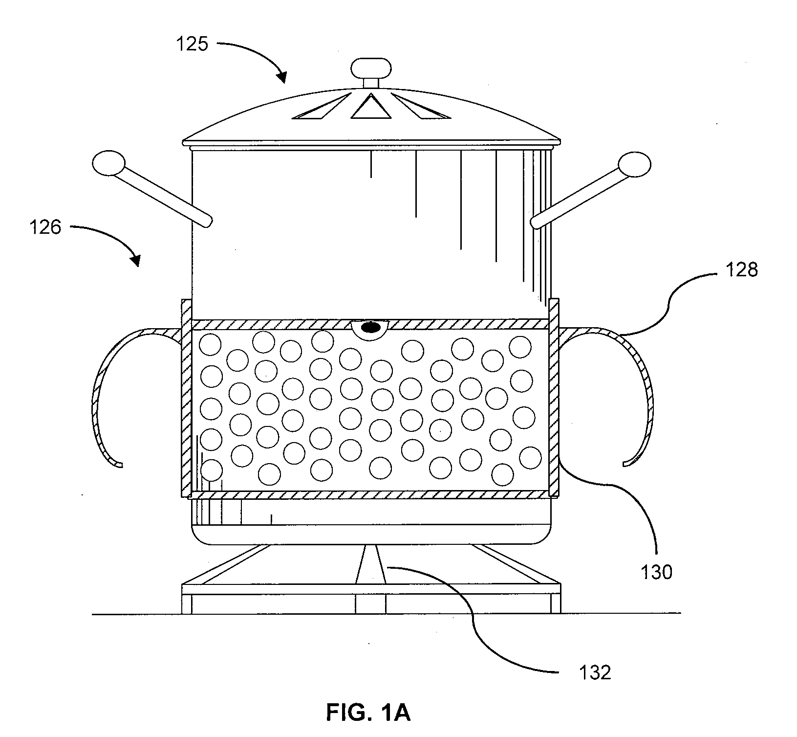
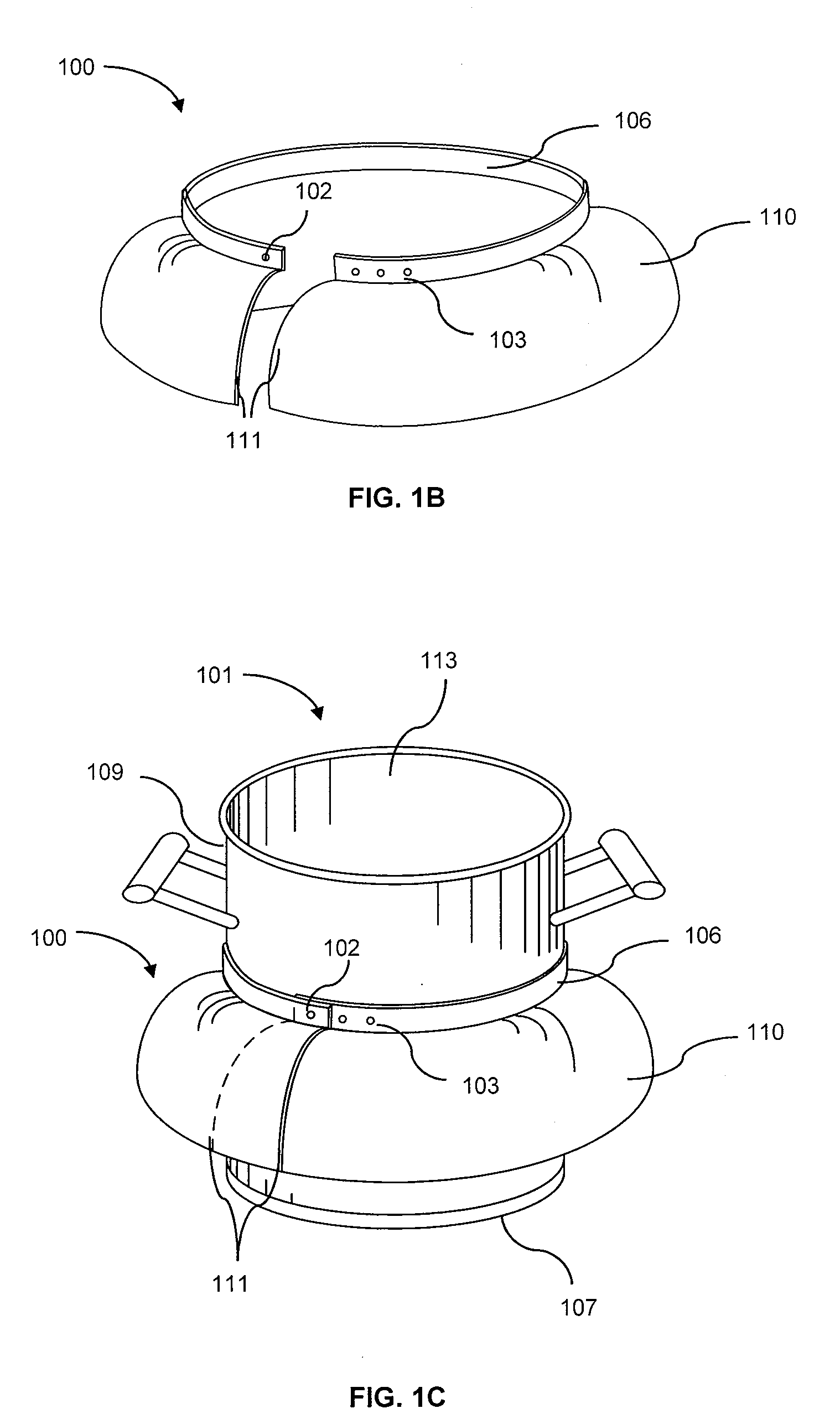
Intervening heat conducting medium
a heat conducting medium and heat exchange technology, applied in the field of cooking vessels, can solve the problems of increasing energy consumption, affecting the efficiency of heating process, and requiring nations to expend considerable resources in conserving energy, so as to improve the ability of cooking vessels, prevent heat loss into the atmosphere, and efficiently utilize heat emitted
- Summary
- Abstract
- Description
- Claims
- Application Information
AI Technical Summary
Benefits of technology
Problems solved by technology
Method used
Image

Examples
Embodiment Construction
[0040]Detailed illustrative embodiments of the invention are disclosed herein. However, techniques, systems and operating structures in accordance with the invention may be embodied in a wide variety of forms and modes, some of which may be quite different from those in the disclosed embodiments. Consequently, the specific structural and functional details disclosed herein are merely representative, yet in that regard, they are deemed to afford the best embodiments for the purposes of disclosure and to provide a basis for the claims herein, which define the scope of the invention. The following presents a detailed description of preferred embodiments (as well as some alternative embodiments) of the invention.
[0041]According to the law of heat flow, heat flows from a hot substance to a cold substance. The colder of two bodies in contact with each other will absorb heat until both objects are the same temperature. Heat may be conducted from one body to another by direct contact of the...
PUM
| Property | Measurement | Unit |
|---|---|---|
| diameter | aaaaa | aaaaa |
| height | aaaaa | aaaaa |
| height | aaaaa | aaaaa |
Abstract
Description
Claims
Application Information