Vibration Reducing Structure for steering wheel

a technology of vibration reducing structure and steering wheel, which is applied in the direction of machine supports, shock absorbers, pedestrian/occupant safety arrangements, etc., can solve the problems of ineffective performance of dynamic damper, inability to achieve good balance between the function of horn switch and the function of dynamic damper, etc., to achieve the effect of reducing the vibration of the steering wheel

Active Publication Date: 2009-09-03
HONDA MOTOR CO LTD +1
View PDF7 Cites 64 Cited by
  • Summary
  • Abstract
  • Description
  • Claims
  • Application Information

AI Technical Summary

Benefits of technology

[0006]The present invention has been made in the light of the above-mentioned circumstances, and it is an object thereof to effectively reduce vibration of a steering wheel with a dynamic damper without affecting the operability of a horn switch.
[0008]With the above-described configuration, the slider is supported on the fixed portion of the steering wheel via the first elastic body so as to be movable in the direction of the axis while the mass is supported on the slider via the second elastic body so as to be movable in the direction perpendicular to the axis. Accordingly, the driver can activate the horn switch by deforming the first elastic body so as to move the slider in the direction of the axis, and the mass vibrates in the direction perpendicular to the axis via the second elastic body with respect to the slider so as to fulfill the function as the dynamic damper, so that vibration of the steering wheel in the direction perpendicular to the axis can be reduced. In this event, since the first elastic body does not affect vibration of the mass in the direction perpendicular to the axis, it is possible to set the spring constant of the first elastic body at a value appropriate for the operation of the horn switch and to set the spring constant of the second elastic body at a value appropriate for the operation of the dynamic damper. As a result, it is possible to effectively reduce the vibration of the steering wheel in the direction perpendicular to the axis with the dynamic damper without affecting the operability of the horn switch.
[0012]With the above-described configuration, since the air bag module, which is provided inside the steering wheel, is utilized as the mass of the dynamic damper, there is no need to provide a dedicated mass. As a result, the configuration contributes to reduction in the number of components, the weight, the installation space, and the cost.

Problems solved by technology

As a result, a problem may occur that the function as the dynamic damper cannot be effectively fulfilled.
Accordingly, as with the above-described conventional example, if the air bag module is supported with a common coil spring both in the direction of the axis and the direction perpendicular to the axis, there is a problem that a good balance between the function as the horn switch and the function as the dynamic damper cannot be achieved.

Method used


Image

  • Vibration Reducing Structure for steering wheel
  • Vibration Reducing Structure for steering wheel
  • Vibration Reducing Structure for steering wheel

Examples


first embodiment

[0027]the present invention will be explained below based on FIGS. 1 to 5B.

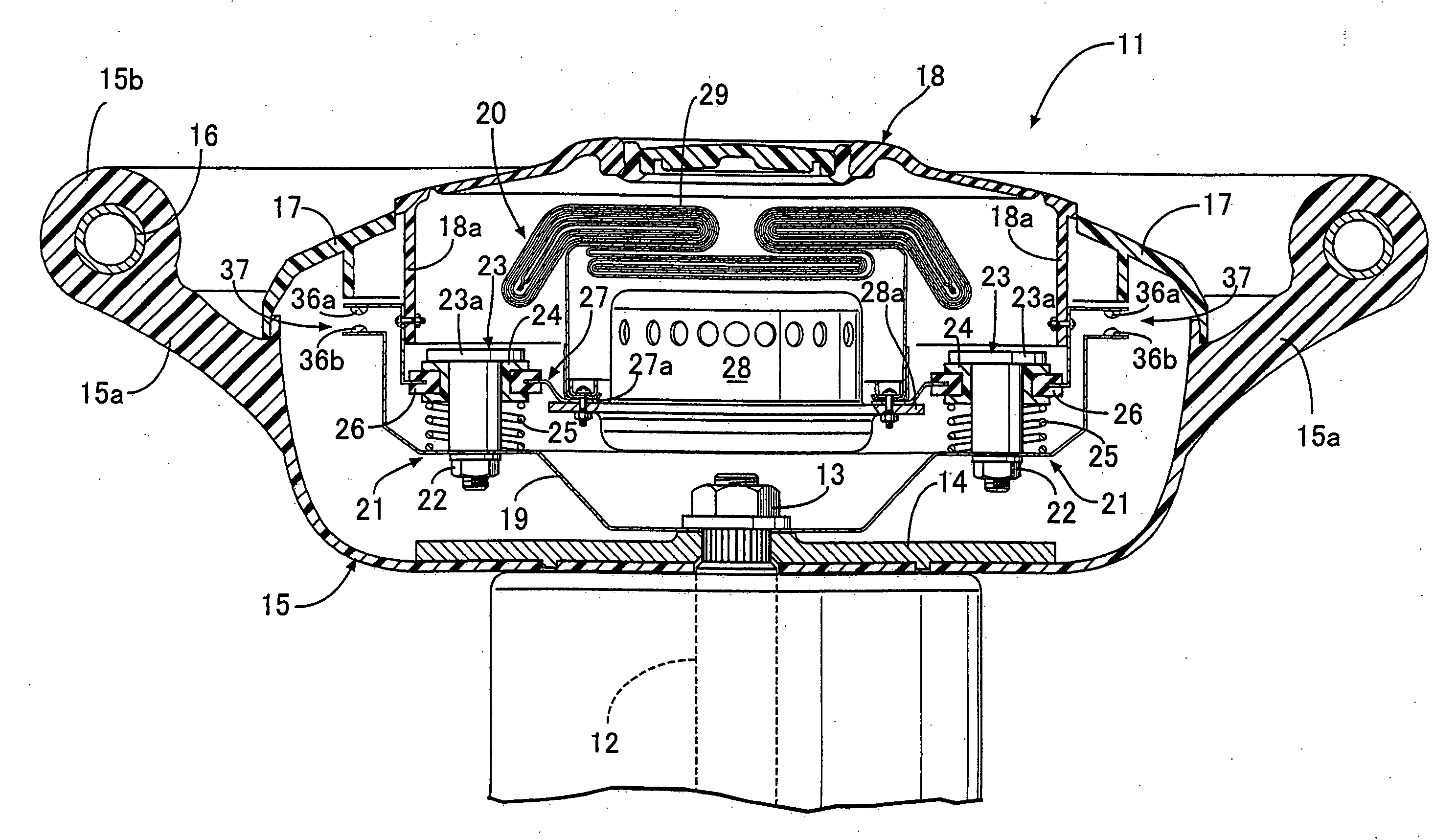
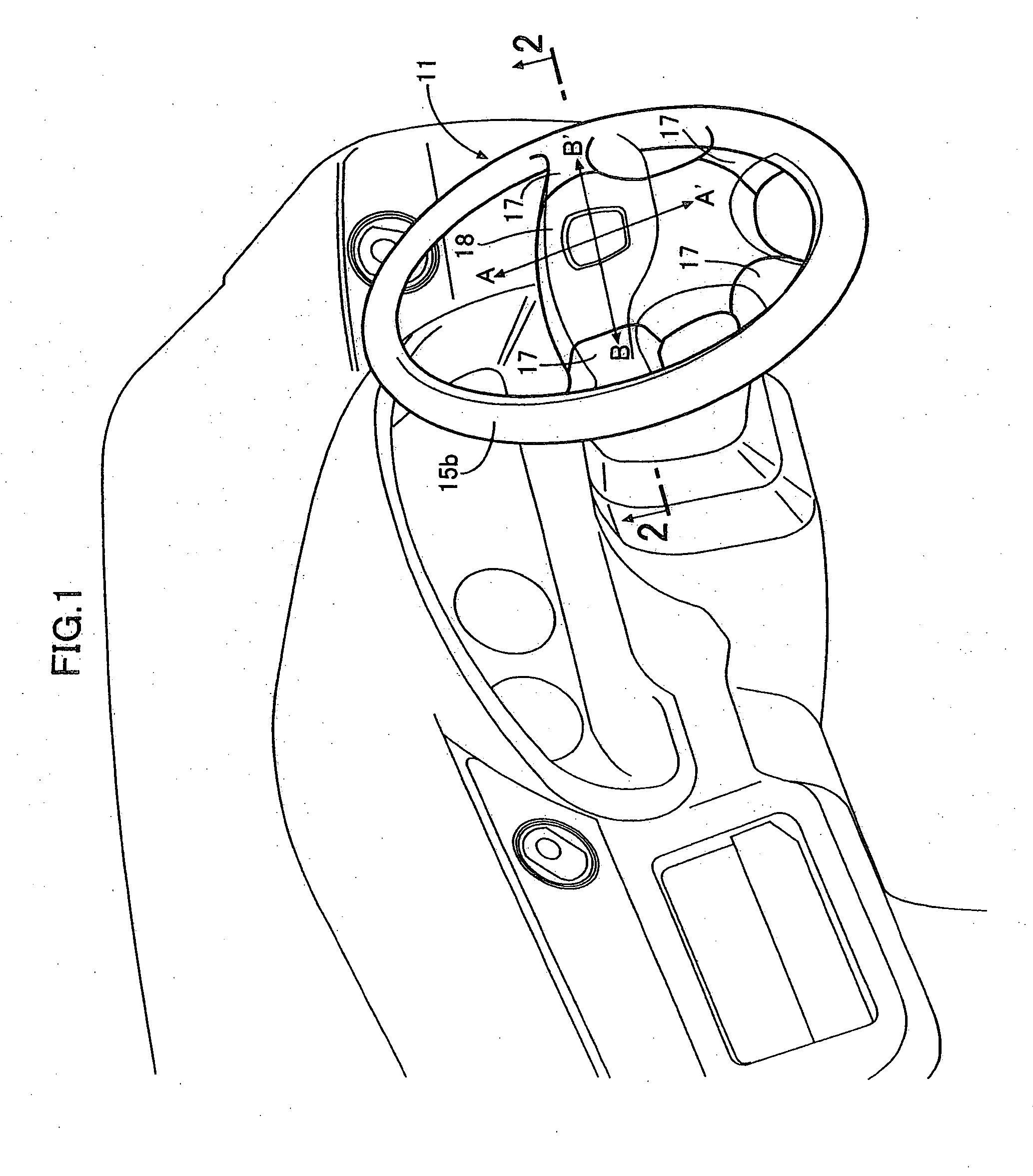
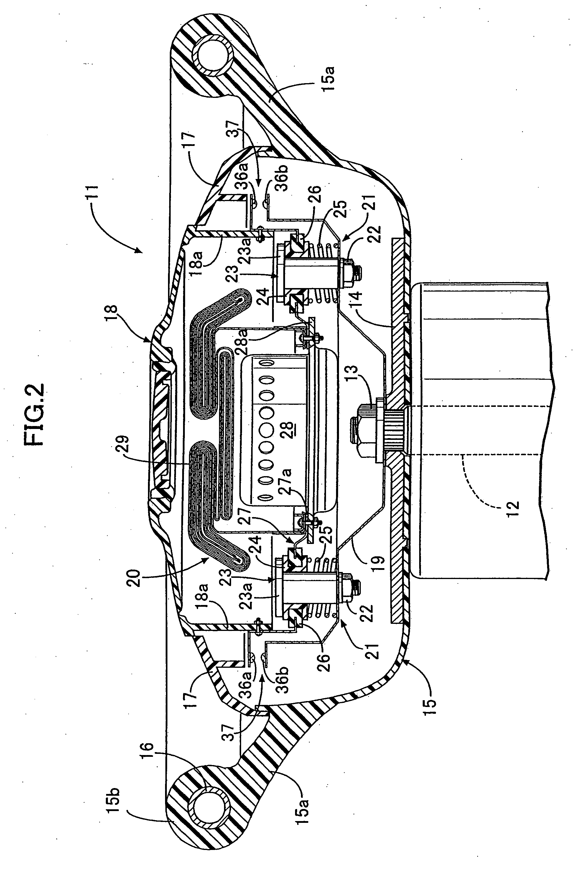
[0028]As illustrated in FIG. 1 and FIG. 2, a steering wheel 11 of an automobile includes a boss member 14, which is made of a disk-shaped metal plate, and which is spline-fitted to a rear end of a steering shaft 12 extending downward from a vehicle interior to the front of a vehicle body, and which is fastened thereto with a nut 13. A cover member 15, which has a container-like shape with an opening rear face, is fixed to cover a front face of the boss member 14. Four spoke portions 15a . . . extend integrally from outer peripheral portions of the cover member 15 outwardly in radial directions, and an annular rim portion 15b is integrally formed on tip ends of the spoke portions 15a . . . A metal ring 16 for reinforcement is buried inside the rim portion 15b. Rear faces of the four spoke portions 15a . . . are covered respectively with spoke-portion covers 17 . . . , and a steering pad 18 is disposed on the i...

second embodiment

[0043]Next, the present invention will be explained based on FIGS. 6 and 7.

[0044]The second embodiment is characterized by the configuration of a slider 24 and a damper spring 26 of a floating support portion 21. The configurations of the other portions are the same as those in the above-described first embodiment.

[0045]The slider 24 of the second embodiment is separated into two parts: a first slider half body 24A and a second slider half body 24B. The first slider half body 24A includes a through-hole 24b loosely fitted onto a periphery of a guide shaft 23, and four locking grooves 24c . . . formed by cutting out the periphery of the through-hole 24b. The upper surface of the first slider half body 24A abuts on the lower surface of a flange 23a of the guide shaft 23. The second slider half body 24B includes a through-hole 24d slidably fitted onto the periphery of the guide shaft 23, and four locking claws 24e . . . protruding from the periphery of the through-hole 24d in the direc...

third embodiment

[0051]Next, the present invention will be explained based on FIG. 8.

[0052]In the above-described first and second embodiments, the guide shafts 23 are supported on the holder 19 side, while the damper springs 26 are supported on the air bag module 20 side. In the third embodiment, guide shafts 23 are supported on the air bag module 20 side, while damper springs 26 are supported on the holder 19 side.

[0053]Specifically, a first retainer 30 has an inner peripheral portion fixed to a flange 28a of an inflator 28 with bolts 32 . . . and nuts 33 . . . , and an outer peripheral portion fixed to a joint portion 18a of a steering pad 18 with bolts 34 . . . and nuts 35 . . . Each guide shaft 23 penetrates a first stay 42 and the first retainer 30, and is fastened thereto with a nut 22, so as to be supported on the air bag module 20 side. The first stay 42 is provided with movable settings 36a of a horn switch 37.

[0054]On the other hand, a second stay 43 is fixed to the holder 19 with bolts 4...


PUM


Abstract

A slider 24 is supported on a holder 19 of a steering wheel 11 via a coil spring 25 so as to be movable in a direction of an axis while an air bag module 20 is supported on a slider 24 via a damper spring 26 so as to be movable in a direction perpendicular to the axis. Since the coil spring 25 does not affect vibration of the air bag module 20 in the direction perpendicular to the axis, it is possible to set a spring constant of the coil spring 25 at a value appropriate for the operation of a horn switch 37, and to set a spring constant of the damper spring 26 at a value appropriate for the operation of the dynamic damper. As a result, it is possible to effectively reduce the vibration of the steering wheel 11 in the direction perpendicular to the axis with the dynamic damper without affecting the operability of the horn switch 37.

Description

BACKGROUND OF THE INVENTION[0001]1. Field of the Invention[0002]The present invention relates to a vibration reducing structure for a steering wheel in which: a mass is supported inside a steering wheel via an elastic body so as to be movable in a direction of an axis and a direction perpendicular to the axis of the steering wheel; a horn switch is activated by pressing the mass in the direction of the axis; and the mass is allowed to vibrate in the direction perpendicular to the axis so as to function as a dynamic damper[0003]2. Description of the Related Art[0004]A steering wheel has been publicly known from Japanese Patent Application Laid-open No. 2006-96127, in which an air bag module is elastically supported via a coil spring inside the steering wheel; the pressing of a pad of the steering wheel by a driver compresses the coil spring in a direction of an axis direction so as to activate a horn switch; and an inflator of the air bag module is supported by another elastic body d...

Claims


Application Information

Patent Timeline
Patent Type & Authority Applications(United States)
IPC IPC(8): B62D1/11F16F15/00F16F7/00B60R21/20B60R21/203B62D1/10B62D7/22
CPCB60R21/2037F16F7/1028B62D7/222
Inventor TERADA, MASASHIKONDOU, TAKASHIUESAKA, TAKAHIROKUNITAKE, YUKIHIROASAI, MORIMASASAITOU, HIDEAKI
Owner HONDA MOTOR CO LTD
Why Eureka
Try Eureka