Eureka AIR delivers breakthrough ideas for toughest innovation challenges, trusted by R&D personnel around the world.

Device for breaking solid material and method of manufacturing a hose element for such a device

a technology of solid material and hose element, which is applied in the direction of disloding machines, construction, building repairs, etc., can solve the problems of limited use, inability to use, and large problem of handling explosives

Inactive Publication Date: 2009-09-03
EMSTONE
View PDF2 Cites 19 Cited by
  • Summary
  • Abstract
  • Description
  • Claims
  • Application Information

AI Technical Summary

Benefits of technology

[0006]The object of the present invention is to provide an expansion device for breaking solid material, such as stone, rock, concrete and the like, in which the drawbacks stated above have been eliminated and by means of which it is thus possible to quickly, simply and cheaply expand drill holes made in stone, rock, concrete or the like to such a degree that the material surrounding the drill holes is caused to break with a directed explosive force.
[0007]This object is achieved by a device for breaking solid material, comprising an expansible hose element which is insertable into a hole in the solid material and has an externally substantially geometrically regular cross-section, said hose element comprising a coupling at least at one of its ends, the device further comprising at least one expansion portion with an expansion chamber. The hose element further comprises an expansion limiter which has a varying radial distance from the outside of the hose element along the circumferential direction of the hose element. The expansion limiter has the advantage of making the hose expand along its entire length whether there is a surrounding resistance or not, i.e. whether a piece of, for instance, the rock in which the hose is arranged splits or not. Furthermore, it makes it possible to insert only part of the hose element into a drill hole. The term “expansion portion” refers to the portion or portions that are arranged radially inwardly of the expansion limiter. In some embodiments of the hose element, there is only one expansion chamber inwardly of the expansion limiter.
[0016]Here follows a description of how an embodiment of the expansion device with an expansion chamber can be designed to obtain the pressure-generating part of the hose element and, in combination with a suitable design, transmit the result to a directed expansion device. At one end of the hose element, a coupling device is arranged to allow the incoming fluid to enter the expansion chamber of the hose element, and in the other end of the hose element an end coupling is arranged, in which a hole is suitably also made so that some kind of adapter can be connected to enable one or more expansion directing means to be interconnected so that they together can generate a long pressure effect, for instance in case of a long drill hole, or be laterally interconnected. To make it possible to use only one expansion means, an end plug is arranged which seals the expansion means so as to stop fluid from leaking.
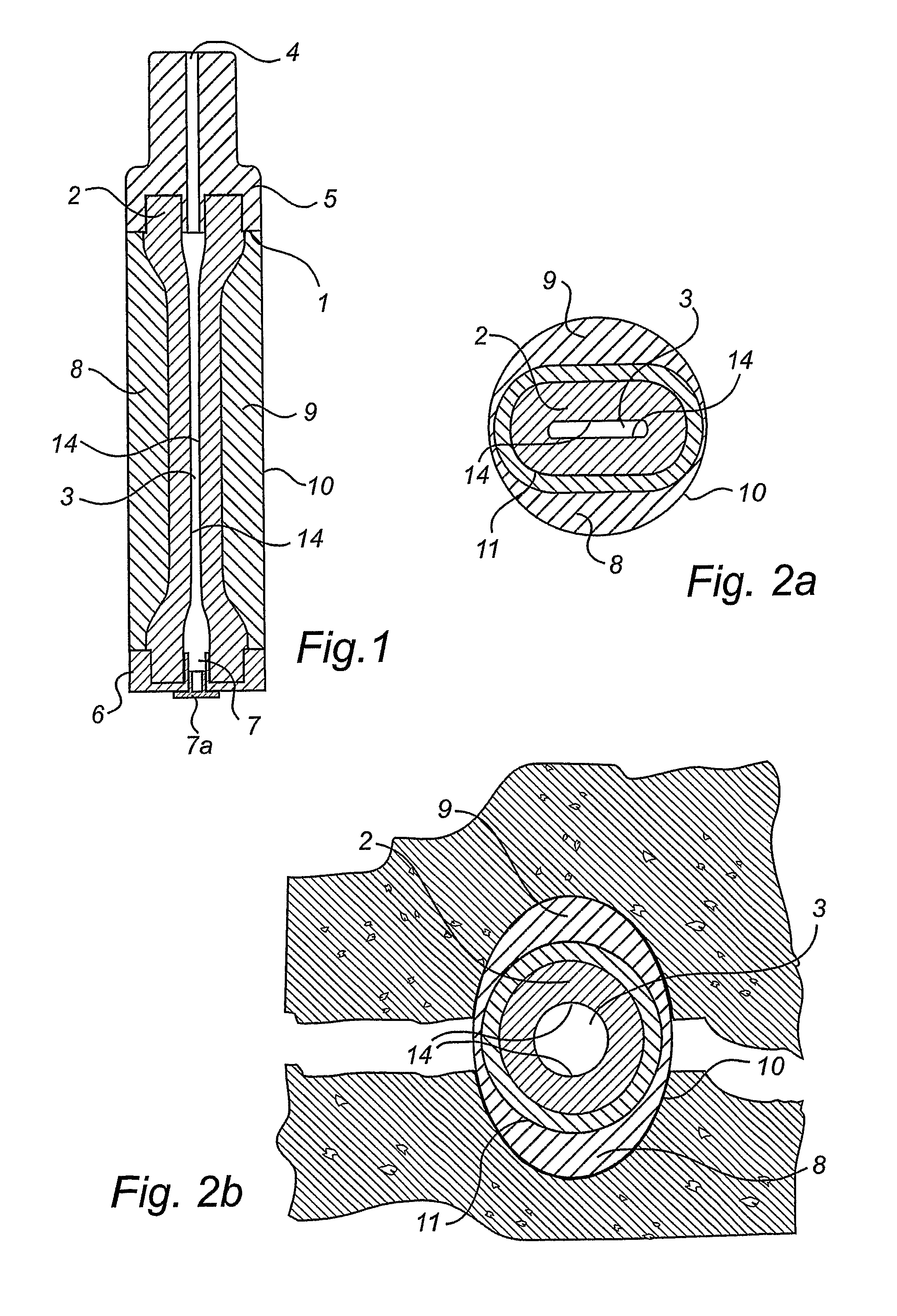
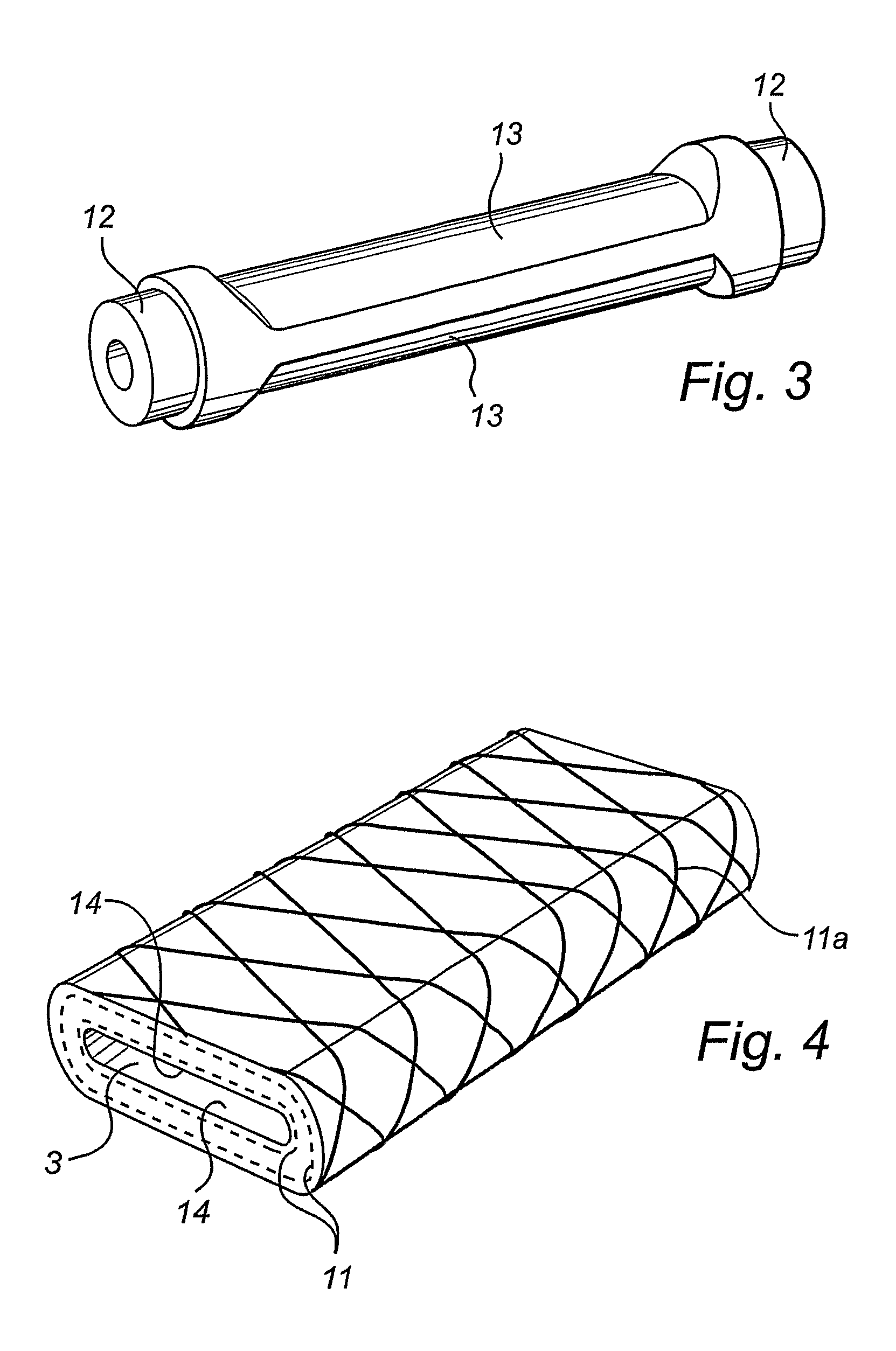
[0017]Means are applied by curing or some other suitable method to the substantially flat outer surfaces of the hose element so that the element obtains the intended shape. In this embodiment, the means have such a shape that the final result is a rounded shape adapted to be inserted in a drill hole. Around the entire expansion means or a suitable portion thereof, an expansible but also contracting casing is suitably arranged by curing, which casing in cooperation with the motion of the hose element is intended to keep together and also protect and above all help the expansion means to return to its initial shape when the pressure in the expansion chamber of the hose element has stopped.

Problems solved by technology

It has for a long time been a great challenge to find a way of cracking rock, stone, concrete and the like in a simple, cheap, quick and environmentally friendly way, while obtaining a predetermined directed expansive force.
However, this method is of limited use, owing to the resultant vibrations, the loud noise and the generally high risks, making it necessary to involve specially trained personnel for the work, and it cannot be used, for instance, in densely built-up areas without great risks or can only be used to a very small extent.
Furthermore, the handling of explosives constitutes a great problem due to the security risks, not only of unintended ignition but also of theft and use of the explosives in illegal operations.
There are, however, important disadvantages of this method, such as the cement being expensive and the breaking taking about 24 hours to perform.
This method requires complicated and expensive devices and may cause problems as the drill hole has to be made absolutely tight before the water is supplied, which means that any cracks in the walls of the drill hole have to be sealed before the breaking can be performed.
In tests, it has also been found that the capsule formed by the pressure chamber has the disadvantage of often splitting into pieces, in particular when the broken material splits or a piece of rock comes off and the capsule is partly uncovered and the pressurisation of the capsule is maintained to make the rock continue to split.
It has been found that in this situation the capsule easily bursts since the surrounding material has disappeared.
This increases the costs as the capsule has to be replaced and, in addition, environmental problems arise since the used fluid is often oil which is released into the environment if the capsule bursts, thereby causing cleaning problems with the collecting of the oil.
It is obvious that this will not work since the metal bars, after being pressed out, will remain in their bent position, in particular at the couplings of the clips.

Method used


Image

  • Device for breaking solid material and method of manufacturing a hose element for such a device
  • Device for breaking solid material and method of manufacturing a hose element for such a device
  • Device for breaking solid material and method of manufacturing a hose element for such a device

Examples


Embodiment Construction

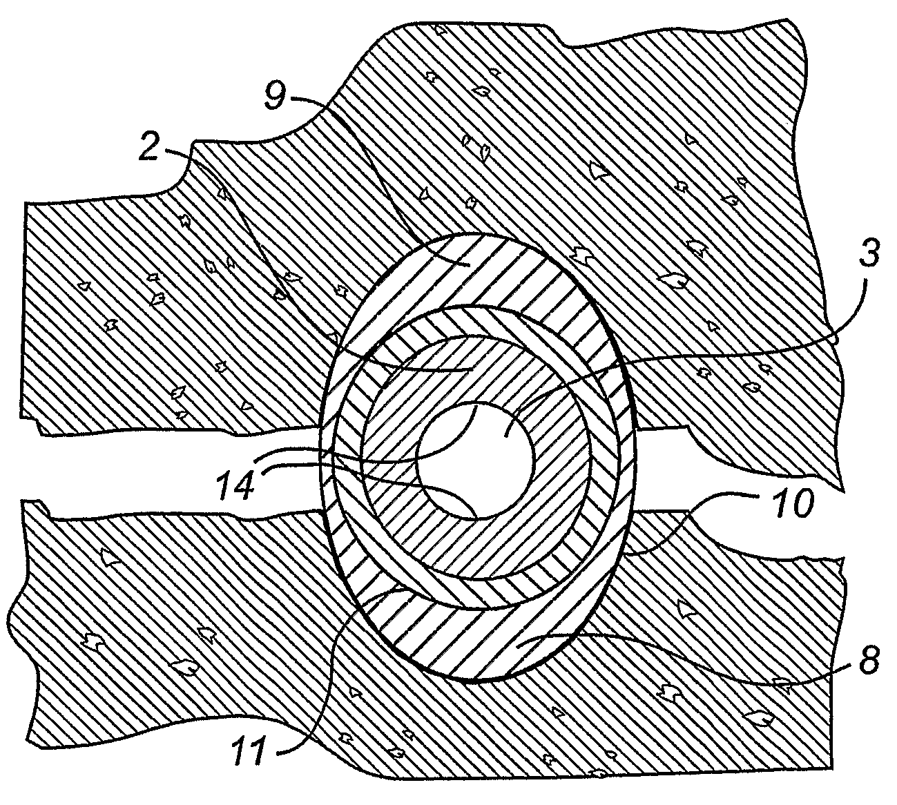
[0028]FIG. 1 shows a device 1, comprising a hose element 2 made of preferably a conventional reinforced hydraulic hose which in its centre portion, seen in the longitudinal direction, is flattened so as to form an expansion chamber 3, which has one or more inner pressure surfaces 14. These broad pressure surfaces 14, which act outwardly seen from the longitudinal axis of the hose element 2 and form the directed pressing part of the hose element 2, generate a high pressure in the initial phase which successively decreases as the hose element 2 returns to a rounded, substantially cylindrical shape. At one of its ends, the hose element 2 has a coupling 5 connected to a pressure source (not shown) from which fluid enters through the opening 4 of the expansion chamber 3 to be subsequently stopped by a coupling 6, which constitutes the stop for the fluid but can be opened if a plug 7a is removed from the opening of the coupling 7. This makes it possible to connect more than one expansion ...


PUM

PropertyMeasurementUnit
radial distanceaaaaaaaaaa
distanceaaaaaaaaaa
cylindrical shapeaaaaaaaaaa

Abstract

A device for breaking solid material comprises an expansible hose element which is insertable into a hole in the solid material and has an externally substantially geometrically regular cross-section. At least at one of its ends, the hose element comprises a coupling. The device further comprises at least one expansion portion with an expansion chamber. The hose element further comprises an expansion limiter which has a varying radial distance from the outside of the hose element along the circumferential direction of the hose element.

Description

TECHNICAL FIELD[0001]The present invention relates to a device for breaking solid material, comprising an expansible hose element which is insertable into a hole in the solid material and has an externally substantially geometrically regular cross-section, said hose element comprising a coupling at least at one of its ends, the device further comprising at least one expansion portion with an expansion chamber. The invention also relates to a method of manufacturing a hose element according to that stated above.TECHNICAL BACKGROUND[0002]It has for a long time been a great challenge to find a way of cracking rock, stone, concrete and the like in a simple, cheap, quick and environmentally friendly way, while obtaining a predetermined directed expansive force.[0003]The breaking of solid materials, such as stone, rock, concrete and the like, can be carried out by drilling one or more holes in the material and by expanding the hole to such a degree that the surrounding material cracks. In...

Claims


Application Information

Patent Timeline
Patent Type & Authority Applications(United States)
IPC IPC(8): E21C37/10B23P11/00
CPCE04G23/08Y10T29/49863E21C37/10E21C37/08
Inventor DERMAN, KARL GUSTAFDERMAN, LENNART
Owner EMSTONE
Why Eureka
Eureka Blog
Learn More