Method and Device for Position Sensing of an Optical Component in an Imaging System

Inactive Publication Date: 2009-09-03
NOKIA CORP
View PDF12 Cites 7 Cited by
  • Summary
  • Abstract
  • Description
  • Claims
  • Application Information

AI Technical Summary

Benefits of technology

[0010]The present invention will become apparent upon reading the description taken in conjunction with FIGS. 2a to 9.

Problems solved by technology

When considering optics for use in a small electronic device, such as mobile phone, the size and cost of the optical sensing components and the suitability to mass production are important issues.

Method used


Image

  • Method and Device for Position Sensing of an Optical Component in an Imaging System
  • Method and Device for Position Sensing of an Optical Component in an Imaging System
  • Method and Device for Position Sensing of an Optical Component in an Imaging System

Examples


Embodiment Construction

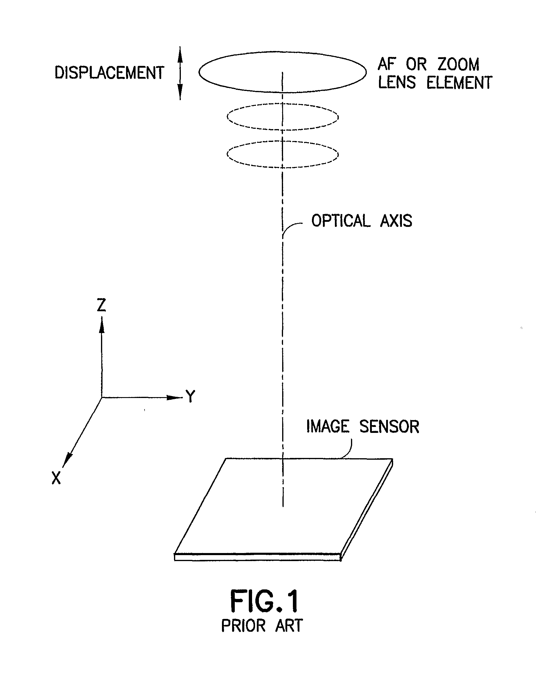
[0024]Imaging applications such as auto-focus lens systems and optical zoom systems require high precision in position sensing. In such applications, at least one lens element is moved along the optical axis of the imaging system so as to change the focal plane of the lens or the magnification of the image formed on an image sensor. As shown in FIG. 1, the movement of the lens element is substantially along the optical axis which is parallel to the Z axis. The image sensor is located in an image plane which is substantially parallel to the XY plane. The imaging system may have one or more stationary lens elements as depicted in dotted lines.

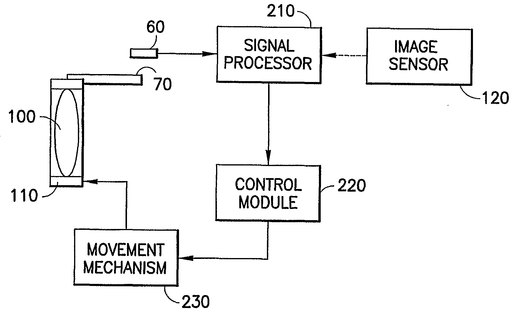
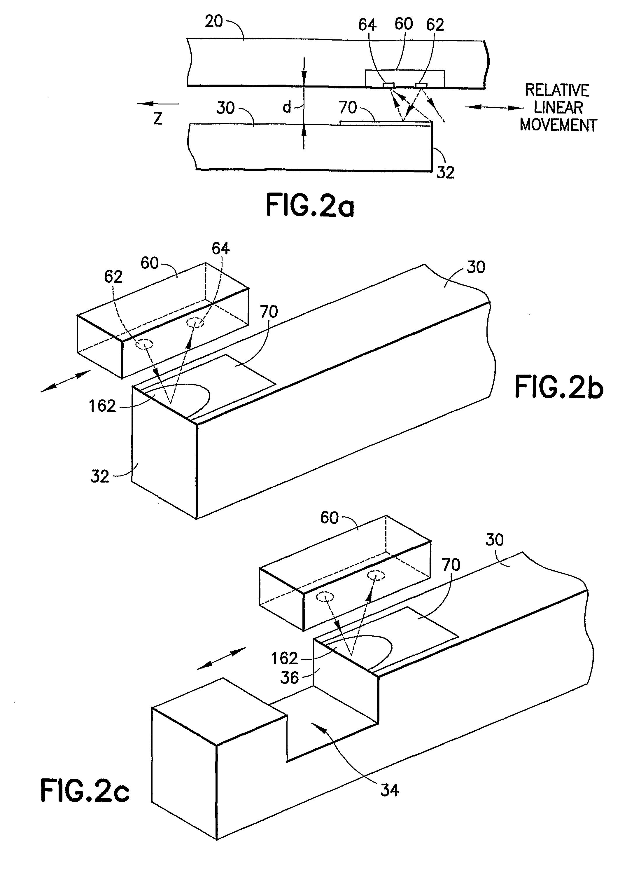
[0025]In auto-focus or optical zoom applications, it is required to determine the position of the lens element relative to a reference point or a home position. According to the present invention, a photo-emitter / sensor pair is used to sense the displacement of the lens element along the Z-axis. As shown in FIG. 2a, a reflection surface 70 is pro...


PUM


Abstract

In a camera where the lens is movable along the optical axis relative to the image sensor for auto-focus or zooming purposes, the lens is moved by a carrier having a carrier portion adjacent to a fixed body portion of the camera. A reflection surface is provided on either the carrier portion or the body portion. A photo-emitter and sensor pair is disposed on the other portion to illuminate the reflection surface and to detect the reflected light therefrom. The reflection surface is provided near the edge of a surface such that the light cone emitted by the photo-emitter partly hits the reflection surface and partly falls beyond the edge. As the lens is moved relative to the body portion, the area on the reflection surface illuminated by the photo-emitter changes causing a change in the amount of detected light.

Description

FIELD OF THE INVENTION[0001]The present invention relates generally to optical position sensing in an imaging system and, more particularly, to position sensing for auto-focus optics and / or an optical zoom module in the imaging system.BACKGROUND OF THE INVENTION[0002]Auto-focus optical systems require high precision in position sensing. In general, needed accuracy is in the order to a few microns. Sensor output linearity and immunity to external disturbances is important. Furthermore, the operation mode for position sensing also requires non-contact operation to avoid mechanical wear. When considering optics for use in a small electronic device, such as mobile phone, the size and cost of the optical sensing components and the suitability to mass production are important issues.[0003]Typically, position determination in a commercial auto-focus module is carried out by counting stepper motor steps. For that purpose, the motor can have an embedded position encoder. In order to reduce t...

Claims


Application Information

Patent Timeline
IPC IPC(8): H04N5/232G02B7/04G02B7/08G03B13/36
CPCG03B13/36G01D5/34746
Inventor KAUHANEN, PETTERI
Owner NOKIA CORP
Why Eureka
Try Eureka