Image forming apparatus and development cartridge

a technology of development cartridges and forming apparatuses, applied in the field of image forming apparatuses, to achieve the effect of improving the detachability of the development cartridge and maintaining the accuracy of reading information

Active Publication Date: 2009-09-03
BROTHER KOGYO KK
View PDF11 Cites 35 Cited by
  • Summary
  • Abstract
  • Description
  • Claims
  • Application Information

AI Technical Summary

Benefits of technology

[0006]As one of advantages, the present invention can maintain accuracy of reading information from the first memory disposed on the development cartridge. As another one of advantages, the present invention can secure a positional relationship between the exposure unit and the photosensitive member. As yet another one of the advantages, the present invention can improve detachability of the development cartridge.

Problems solved by technology

In case of the non-laser type image forming apparatus, the exposure unit has to be disposed closer to the photosensitive member because of light intensity limitation.

Method used


Image

  • Image forming apparatus and development cartridge
  • Image forming apparatus and development cartridge
  • Image forming apparatus and development cartridge

Examples


embodiment 1

[0017]A description is given of embodiment 1 of the present invention with reference to FIG. 1 through FIG. 6.

1. Entire Configuration of Printer

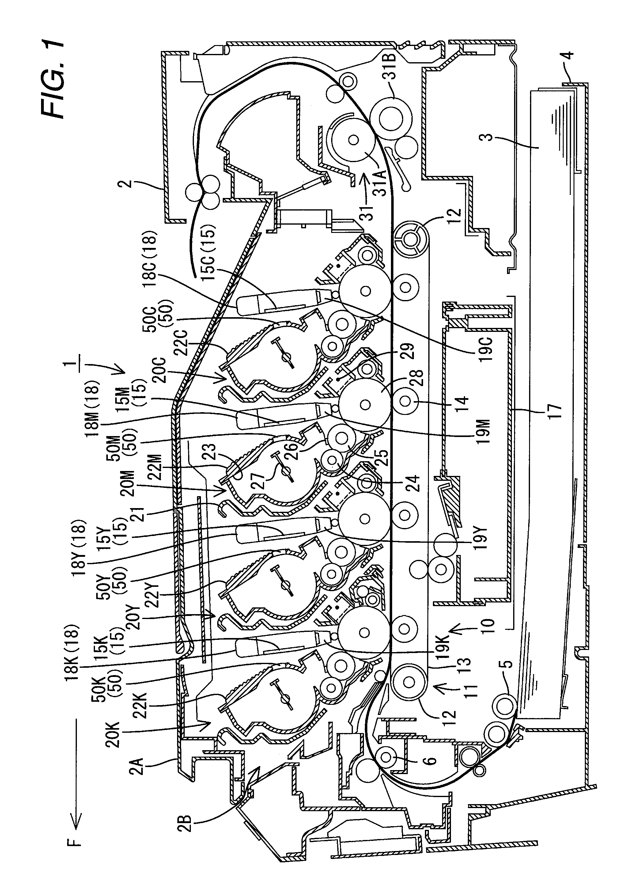
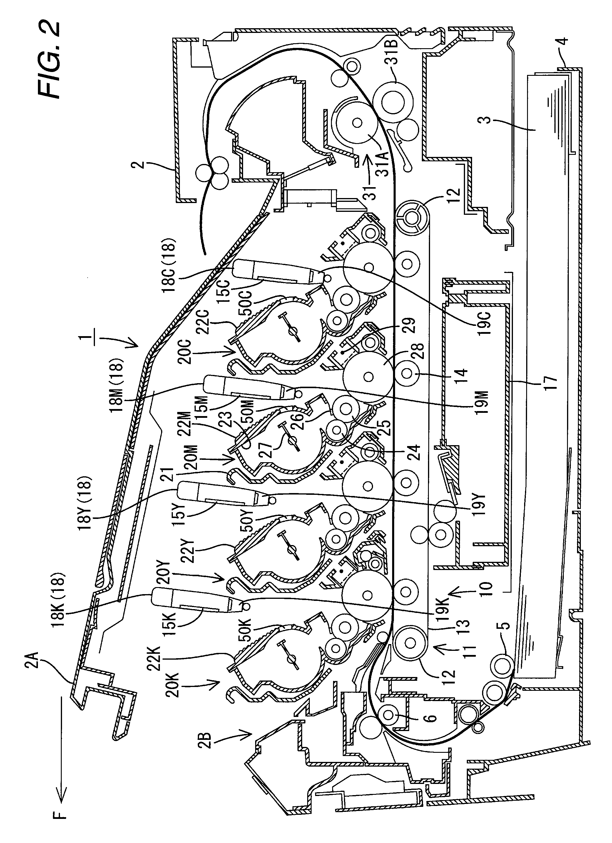
[0018]FIG. 1 and FIG. 2 are side sectional views showing a brief configuration of a printer 1 (one example of an image forming apparatus) according to the present embodiment. In the following description, the left direction of the paper of FIG. 1 and FIG. 2 is the front direction that is shown as F direction in the respective drawings. In this embodiment, the printer 1 is configured as a color printer for forming a color image by four colors of toner (black K, yellow Y, magenta M and cyan C). Hereinafter, where respective components are distinguished color by color, K (black), Y(yellow), M(magenta) and C(cyan) that signify respective colors are added to the end of reference numerals of the components. The image forming apparatus according to the present invention may be configured to use a single color (black) or five or more colors.

[0019]Th...

embodiment 2

[0053]FIG. 7 shows Embodiment 2. A difference from Embodiment 1 described above resides in the location and configuration of the reader unit, and all the other portions are the same as those of Embodiment 1. Therefore, the components are given the same reference numerals, and overlapping description thereof is omitted. A description is given below of only the different points.

[0054]As shown in FIG. 7, an antenna 74 is provided on the LED-mounted substrate 71. A through hole 80 is formed at one end part of the LED-mounted substrate 71. The antenna 74 has an annular shape surrounding the through hole 80. The antenna 74 receives high frequency signals from the control circuit via a circuit pattern on the LED-mounted substrate 71 and induces a high frequency magnetic field to wirelessly receive cartridge information from the IC chip 50 upon.

[0055]Since the antenna 74 is provided on the LED-mounted substrate 71, it is not required to provide a circuit substrate exclusive for the antenna ...

embodiment 3

[0056]FIG. 8 and FIG. 9 show Embodiment 3. A difference from Embodiment 1 described above resides in the location and configuration of the reader unit, and all the other portions are the same as those of Embodiment 1. Therefore, the components are given the same reference numerals, and overlapping description thereof is omitted. A description is given below of only the different points. The LED 70 is omitted in FIG. 8. FIG. 9 is a perspective view of the guide mechanism 52 described above when viewed from above.

[0057]The LED-mounted substrate 71 has a memory 85 (for example, EEPROM, one example of a second memory) in which the LED information (one example of a light emitting portion information) is stored. The memory 85 is electrically connected to the CPU 40 via an information signal path 86 formed on the LED-mounted substrate 71. The “LED information” includes the light emitting amount information of each of the LEDs 70 and the position information thereof. The CPU 40 reads the LE...


PUM


Abstract

An image forming apparatus is provided. A development cartridge having a first memory storing therein cartridge information is detachably mountable to the image forming apparatus. The image forming apparatus includes: an apparatus casing and an exposure unit having plural light emitting portions. The exposure unit is supported by the apparatus casing so that the light emitting portions face a photosensitive member rotatably supported by the apparatus casing. The image forming apparatus further includes a reader unit disposed on the exposure unit and configured to read the cartridge information from the first memory when the development cartridge is mounted to the image forming apparatus.

Description

CROSS REFERENCE TO RELATED APPLICATION[0001]The present disclosure relates to the subject matter contained in Japanese patent application No. 2008-050493 filed on Feb. 29, 2008, which is expressly incorporated herein by reference in its entirety.TECHNICAL FIELD[0002]The present invention relates to an image forming apparatus. The present invention also relates to a development cartridge detachably mountable to the image forming apparatus.BACKGROUND ART[0003]As disclosed, for example, in JP2007-52055A, an electrophotographic image forming apparatus, such as a laser printer, can be configured to have a replaceable development cartridge having a memory (IC chip). When the development cartridge is mounted on the printer, the printer can read information from the memory for printing control. For example, the development cartridge memory stores information indicative of whether or not the development cartridge is brand-new, and an antenna on the printer reads the information stored in the...

Claims


Application Information

Patent Timeline
Patent Type & Authority Applications(United States)
IPC IPC(8): G03G15/00
CPCG03G15/326G03G2215/0697G03G2221/1651G03G2221/1823G03G21/1657G03G15/0855G03G21/1676G03G15/04054G03G15/0863G03G15/0896G03G15/0865G03G21/1666
Inventor FUNAHASHI, NORIMICHI
Owner BROTHER KOGYO KK
Why Eureka
Try Eureka