Device for cleaning of crankcase gases

a technology for cleaning devices and crankcases, which is applied in auxillary pretreatment, centrifuges, separation processes, etc., can solve the problems of affecting the sealing of the gaskets of the crankcase, reducing the gas pressure in the crankcase to an unallowably low level, and pumping too much crankcase gas out of the crankcas

Active Publication Date: 2009-09-10
ALFA LAVAL CORP AB
View PDF8 Cites 36 Cited by
  • Summary
  • Abstract
  • Description
  • Claims
  • Application Information

AI Technical Summary

Benefits of technology

[0021]Also by means of this combination of features it may be ensured that a desired gas pressure is maintained in the crankcase during operation of the device and the combustion engines. It is possible to prevent in a reliable manner that the gas pressure sinks below a predetermined minimum level or rises above a predetermined maximum level. Thanks to the fact that the device comprises two possibilities to compensate for a changed gas pressure, the device is suitable to be used in all kinds of combustion engines, and more specifically both in such engines that are operated at a subpressure in the crankcase and such engines that are operated at an overpressure in the crankcase. By means of the defined rotary speed control, it may be prevented that the gas pressure in the crankcase exceeds a too high unallowable level by an increase of the rotary speed of the drive device. By means of the defined import conduit it is possible to prevent in a reliable manner that the gas pressure in the crankcase goes below a too low unallowable level.

Problems solved by technology

One problem associated with the cleaning of crankcase gases deals with maintaining a desired gas pressure in the crankcase.
There is a risk of pumping too much crankcase gas out of the crankcase by means of the centrifugal separator, wherein the gas pressure in the crankcase may decrease to an unallowably low level, and for instance be significantly below the surrounding atmospheric pressure.
This can have a negative influence on the gaskets sealing the crankcase.
In addition, contaminated air can be sucked into the crankcase and give rise to damage.
In certain situations there is also a risk that the centrifugal separator would not be able to pump away a sufficient quantity of crankcase gas so that the gas pressure in the crankcase increases to an unallowably high level, significantly above the surrounding atmospheric pressure.
This can also have a negative influence on the gaskets and in some cases lead to leakage of crankcase gas from the crankcase of the combustion engine.

Method used


Image

  • Device for cleaning of crankcase gases
  • Device for cleaning of crankcase gases
  • Device for cleaning of crankcase gases

Examples


first embodiment

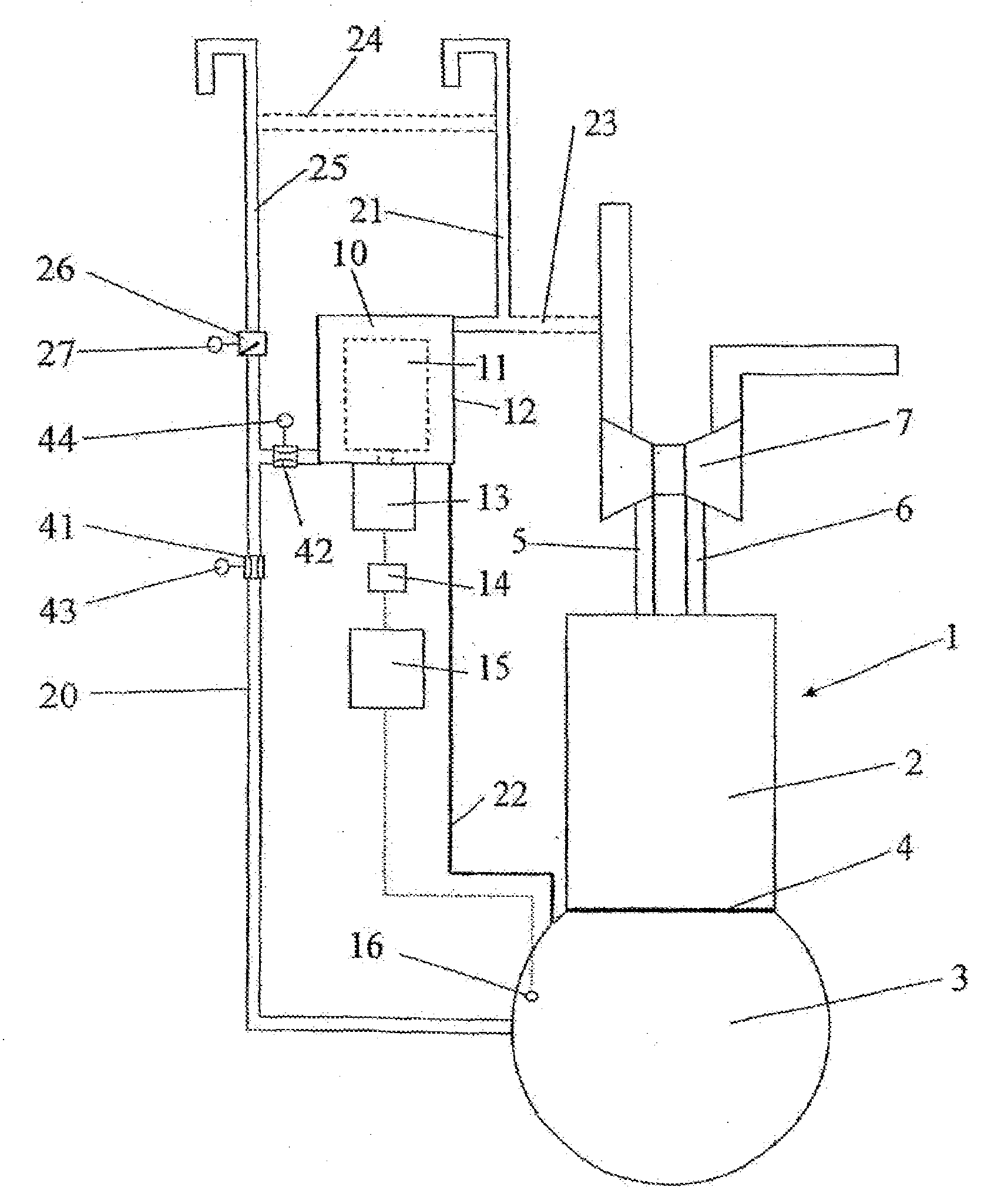
[0035]FIG. 1 illustrates the invention according to which the device comprises an electric motor 13 having a controllable rotor speed for quick control of the rotary speed of the centrifuge rotor 11, and the above explained export conduit 25.

second embodiment

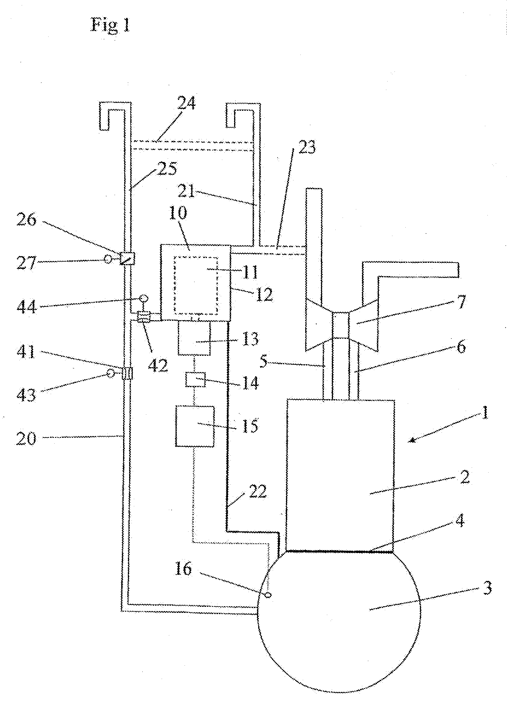
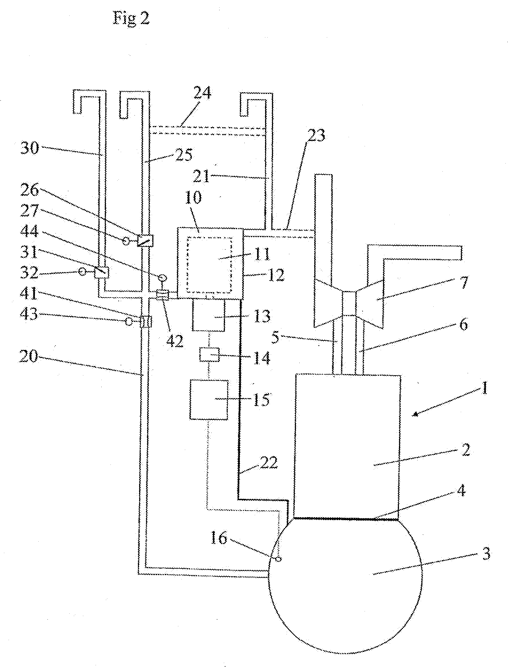
[0036]FIG. 2 illustrates the invention according to which the device in addition to the electric motor 13 and the export conduit 25 also comprises the above explained import conduit 30.

[0037]FIG. 3 illustrates a third embodiment of the invention according to which the device comprises the above explained export conduit 25 and the above explained import conduit 30. In the third embodiment, a simpler variant of the drive device 13, however, is used for driving the centrifuge rotor 11, and more specifically a drive device 13 without a controllable rotary speed. Such a drive device 13 may be realised by means of an electric motor of suitable kind or a motor driven by means of any fluid, for instance oil from the oil system for the combustion engine 1. Examples of different variants of drive devices 13 and the driving of the device 13 are disclosed in the above-mentioned WO99 / 56883.

fourth embodiment

[0038]FIG. 4 illustrates the invention according to which the device comprises the above explained import conduit 30 and an electric motor 13 having a rotary speed control.


PUM

PropertyMeasurementUnit
rotary speedaaaaaaaaaa
pressureaaaaaaaaaa
opening pressureaaaaaaaaaa

Abstract

This document describes a device for cleaning of crankcase gases from a combustion engine, and a combustion engine having such a device. An inlet conduit is connected to a crankcase of the combustion engine. A centrifugal separator receives a flow of crankcase gases from the crankcase via the inlet conduit and comprises a routable centrifuge rotor for centrifuging the crankcase gases. A drive device drives the centrifuge rotor. An outlet conduit discharges cleaned crankcase gases from the centrifugal separator. The rotary speed of the drive device, and thus the rotary speed of the centrifuge rotor, is controllable depending on the gas pressure in the crankcase. An export conduit may be connected to the inlet conduit and adapted to enable discharge of a flow of crankcase gases from the crankcase by-passing the centrifugal separator depending on the gas pressure in the crankcase. An import conduit may be connected to the inlet conduit and adapted to enable feeding of a flow of air from the surroundings to the crankcase depending on the gas pressure in the crankcase.

Description

THE FIELD OF THE INVENTION[0001]The present invention refers generally to the cleaning of crankcase gases from a combustion engine, for instance large combustion engines for ships and stationary installations, such as combustion engines for generators, and combustion engines for vehicles such as trucks.[0002]More specifically, the present invention refers to a device for cleaning of crankcase gases from a combustion engine, comprising an inlet conduit, which is adapted to be connected to a crankcase of the combustion engine, a centrifugal separator, which is adapted to receive a flow of crankcase gases from the crankcase via the inlet conduit and which comprises a rotatable centrifuge rotor for centrifuging the crankcase gases, a drive device, which drives the centrifuge rotor, and an outlet conduit, which is adapted to discharge cleaned crankcase gases from the centrifugal separator.BACKGROUND OF THE INVENTION[0003]One problem associated with the cleaning of crankcase gases deals w...

Claims


Application Information

Patent Timeline
Patent Type & Authority Applications(United States)
IPC IPC(8): F02B25/06B01D45/14B01D50/00B04B9/10F01MF01M13/04
CPCB01D45/14B04B9/10F01M2013/0422F01M2013/0083F01M13/04B04B5/08F02B77/04
Inventor BORGSTROM, LEONARDCARLSSON, CLAES-GORANMOBERG, HANSSKOOG, JANHAGGMARK, CARL
Owner ALFA LAVAL CORP AB
Why Eureka
Try Eureka