
Safety buckling cover

a safety buckling and cover technology, applied in the field of cups, can solve the problems of difficult user understanding of pushing and pressing, inconvenient operation, and inability to securely secure the sealing block, and achieve the effect of enhancing the structure of the cover of the cup

Inactive Publication Date: 2009-09-10
WANG YU TZU
View PDF4 Cites 25 Cited by
  • Summary
  • Abstract
  • Description
  • Claims
  • Application Information

AI Technical Summary

Benefits of technology

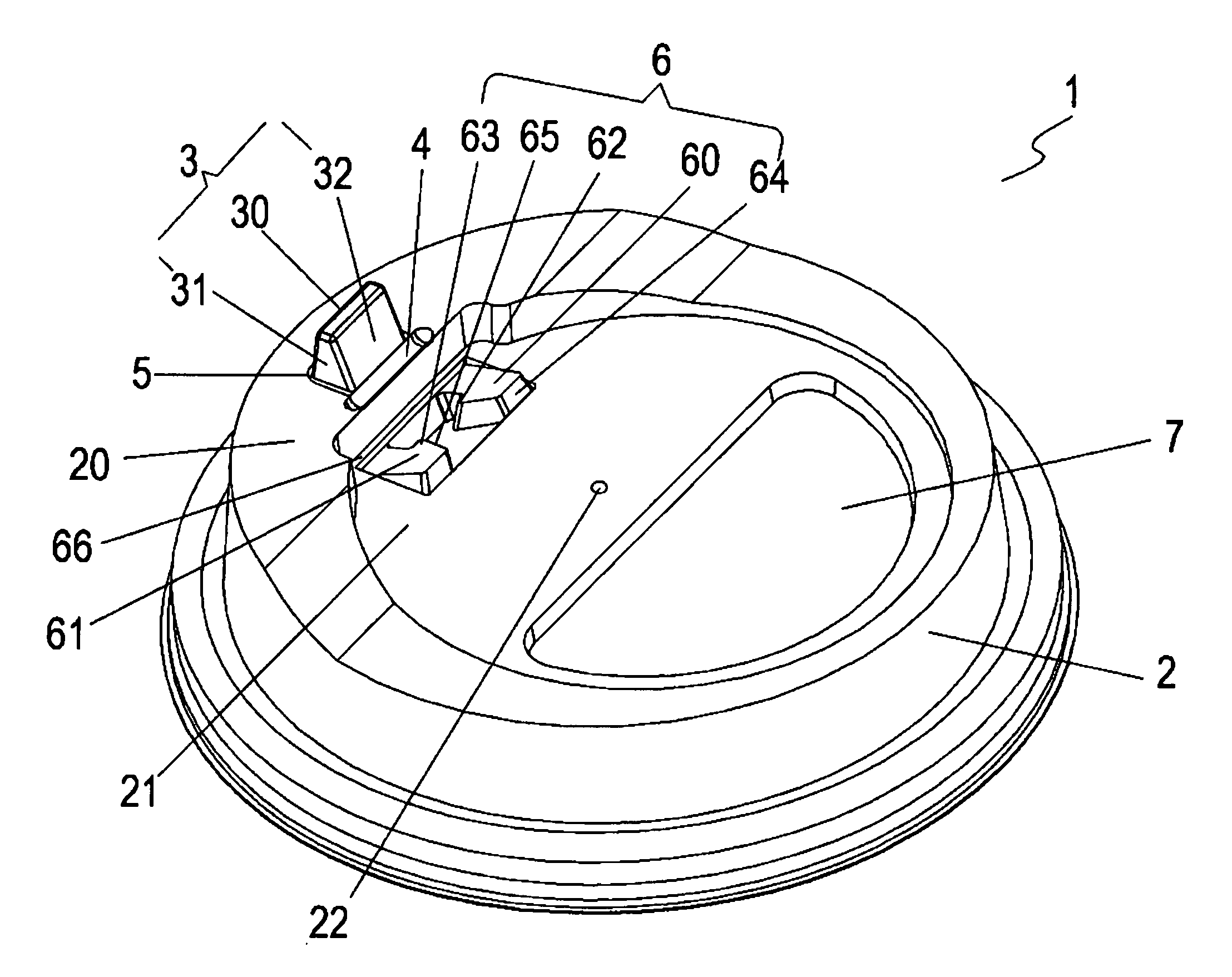
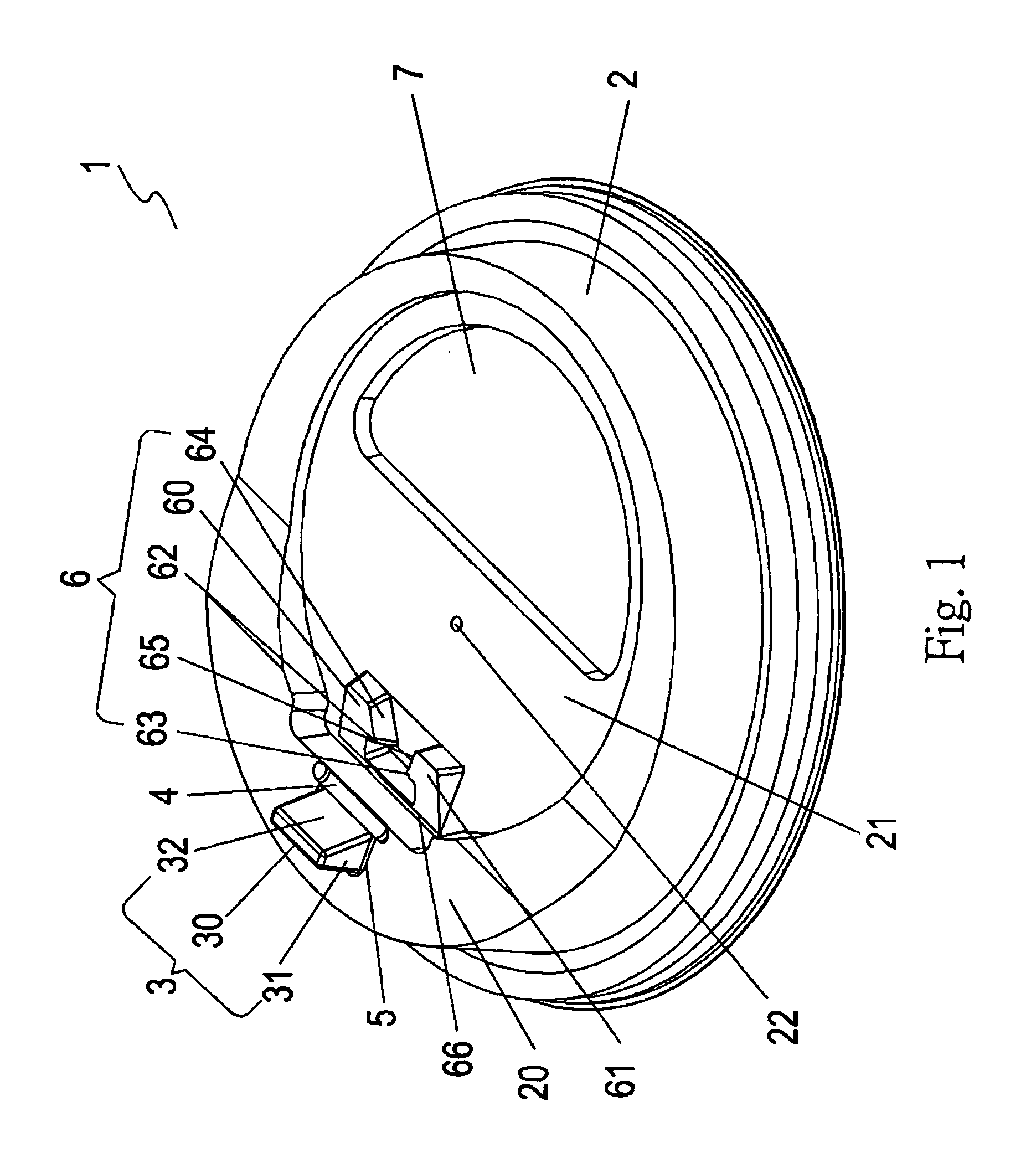
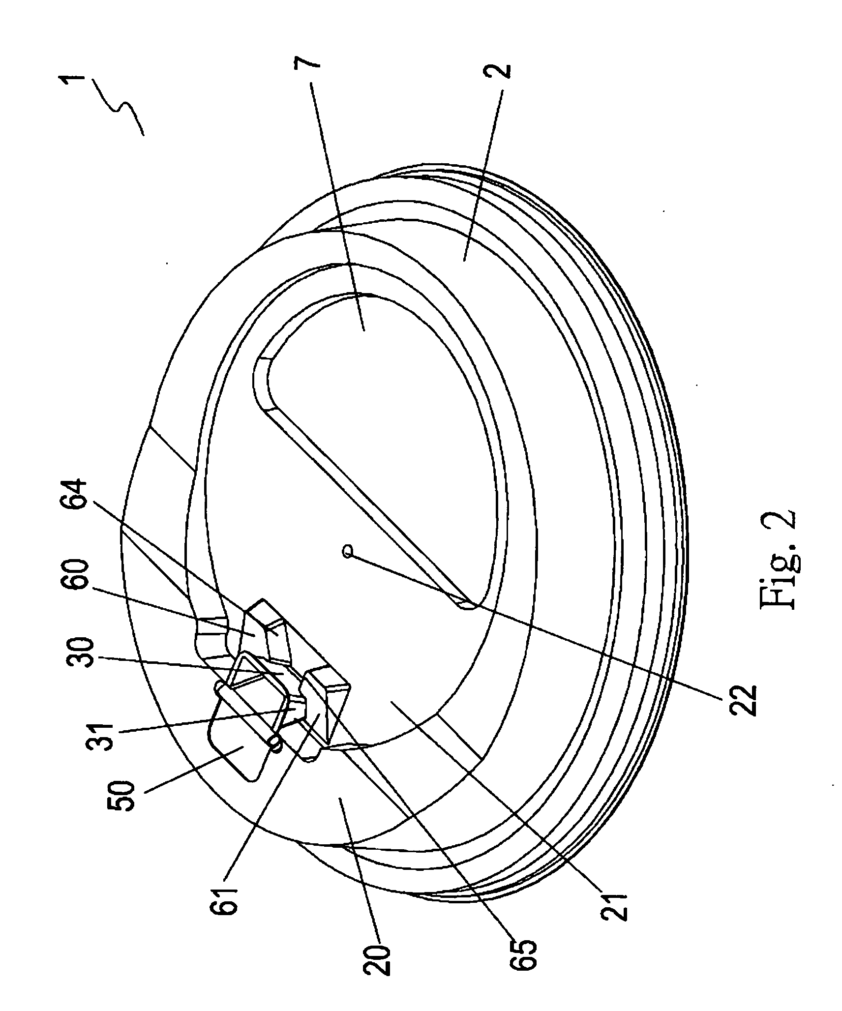
[0008]Accordingly, the object of the present invention is to provide a safety buckling cover which has a buckle. The buckle includes two hook blocks for safely clamping a movable unit therebetween to prevent from releasing out. A front lateral side of each hook block has an inclined surface for guiding the movable unit into the space between the two hook blocks. Moreover, the present invention includes a rib which is a semi-round recess for enhancing the structure of the cover of a cup.
[0015]A rib being a semi-round recess for enhancing the structure of the cover; and the cover surface also formed with a vent for venting air.
[0023]By above mentioned structure, when the movable unit separates from a frame top of the cup cover so as to form with a drinking opening and is buckled between the two hook blocks, the user can drink the juicy in the cup safely. Therefore, the present invention has the effect of avoiding the movable unit from releasing.

Problems solved by technology

However by a recess to buckle the seal block has the defect that the sealing block can not be firmly secured.
The operation is very inconvenient.
1. The sealing block is buckled in the embedding groove, the operation of pushing and pressing is difficult for the user to understand.
It is inconvenient for the user to apply a force thereto.
It is easy to break due to an improper force applied thereto.

Method used


Image

  • Safety buckling cover
  • Safety buckling cover
  • Safety buckling cover

Examples


Embodiment Construction

[0035]In order that those skilled in the art can further understand the present invention, a description will be provided in the following in details. However, these descriptions and the appended drawings are only used to cause those skilled in the art to understand the objects, features, and characteristics of the present invention, but not to be used to confine the scope and spirit of the present invention defined in the appended claims.

[0036]Referring to FIGS. 1 to 4, the structure of the present invention is illustrated. The present invention has the following elements.

[0037]A safety buckling cover 1 is capable of being buckled into a cup. The cover 1 has an outer frame 2 which is installed at an upper side of the cover 1. A frame top 20 of the outer frame 2 is installed with a movable unit 3. A central portion of the cover 1 is formed with a cover surface 21.

[0038]The movable unit 3 is approximately vertical to the frame top 20 and is formed with a push portion 30 at one side t...


PUM


Abstract

A safety buckling cover includes an outer frame installed at an upper side of the cover; a frame top of the outer frame being installed with a movable unit; the movable unit being approximately vertical to the frame top and being formed with a push portion at one side thereof; each of two lateral sides of the movable unit being installed with a buckle; the two buckles tightly clamping the movable unit from the two lateral sides thereof; a buckle including two hook blocks; each of the hook blocks having a respective protruding edge resisting against the movable unit for safely clamping the movable unit to prevent the movable unit from releasing out; the front inner lateral side of each hook block having an inclined surface for guiding the movable unit to enter into a space between the two hook blocks.

Description

FIELD OF THE INVENTION[0001]The present invention relates to cups, and particularly to a safety buckling cover for a cup. The cover is integrally formed with a buckle which is formed by two hook blocks. The two hook blocks are arranged oppositely so as to form with a clamping portion. A front lateral side of each hook block has a rib which has a semi-round shape for enhancing the structure of the whole cup.BACKGROUND OF THE INVENTION[0002]Conventional cup cover has an outer edge and a sealing block. An inner edge of the cover has an embedding groove. When driving the sealing block to break the breaking line so as to fold inwards, the sealing block can be embedded into the embedding groove in the cup cover directly.[0003]However by a recess to buckle the seal block has the defect that the sealing block can not be firmly secured. Only two sides thereof are clamped. The resilient force from the sealing block after bending can not be released. As the sealing block returns elastically, i...

Claims


Application Information

Patent Timeline
Patent Type & Authority Applications(United States)
IPC IPC(8): B65D43/02
CPCB65D43/0212B65D47/0847B65D2251/1008B65D2543/00046B65D2543/00092B65D2543/00796B65D2543/00351B65D2543/00379B65D2543/00527B65D2543/00537B65D2543/00731B65D2543/00296
Inventor WANG, YU-TZU
Owner WANG YU TZU
Learn More